Sierra Video Ponderosa 3G Series Routing Switcher Family with MediaNav User Manual
Page 27
PONDEROSA
21
GPI
The 25 pin D connector on the rear of the Master CPU frame provides relay contacts
under software control that can be used to indicate a failure of router frame power
supplies and fans.
The female 25 pin D connector on the rear of the CPU frame provides access to 5 relay
contact sets (GPI-out 0-4). These contact sets are used to indicate failures in the router
frames.
The female 25 pin D connector also provides for “GPI inputs” where an external contact
closure can cause an “event”. GPI inputs need to be grounded to initiate event.
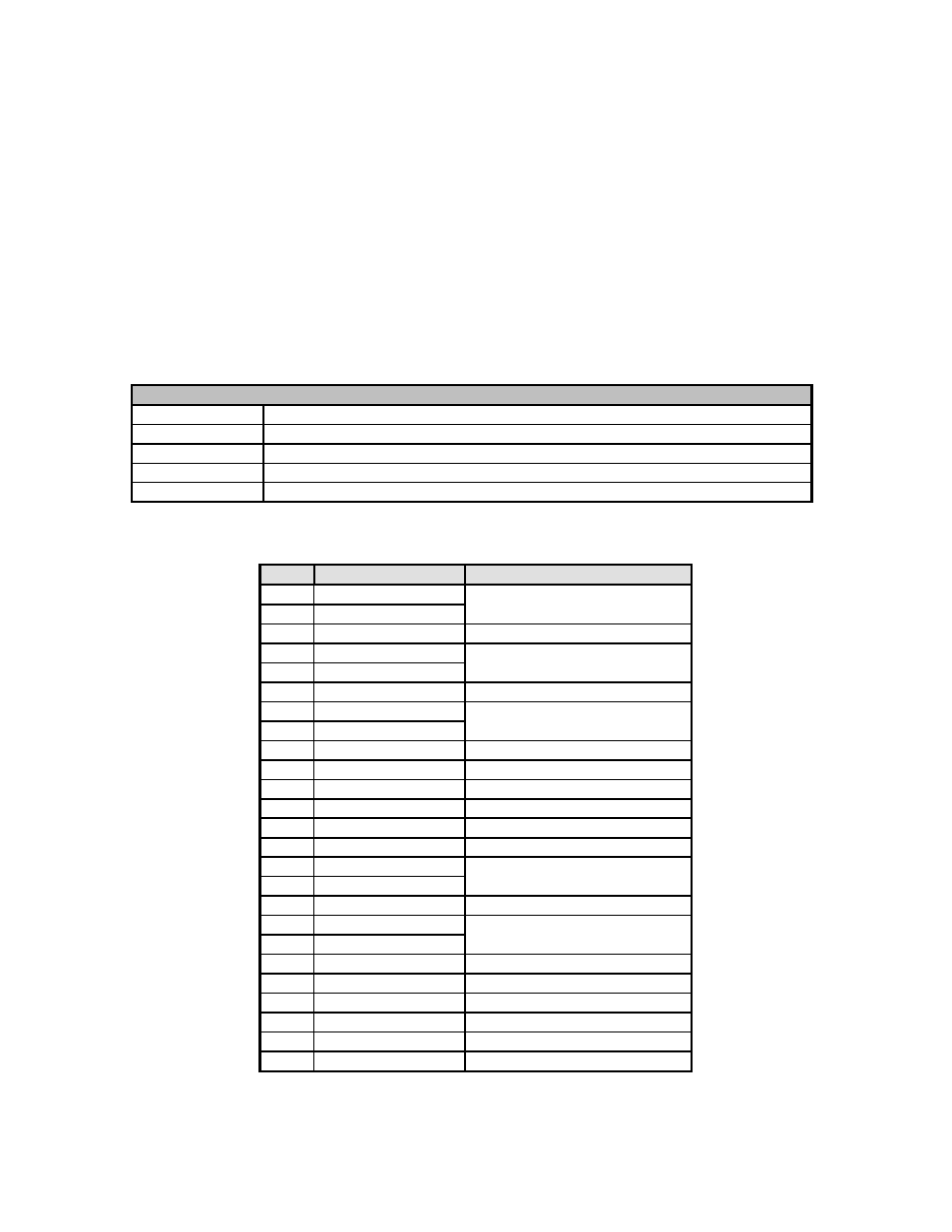
The GPOs are defined to behave as follows:
Name
Function
GPO-0
Open when power supply 1 is on; closed otherwise
GPO-1
Open when power supply 2 is on; closed otherwise
GPO-2
Open when the fans for power supply 1 are functioning; closed otherwise
GPO-3
Open when the fans for power supply 2 are functioning; closed otherwise
GPO-4
Open when Error LED is on; closed otherwise (See Note in Section 5.1)
GPI/O settings are described in the chart below;
* Contact the SVS Factory for “Future Use” updates.
Pin #
Connection
Alarm Description
1
GPI-4 out N/O
* Future Use
2
GPI-4 out Common
3
N/C Not
Used
4
GPI-2 out N/O
Failure- Fan Power Supply # 1
5
GPI-2 out Common
6
N/C Not
Used
7
GPI-0 out N/O
Failure- Power Supply # 1
8
GPI-0 out Common
9
GPI-4 in
* Future Use
10
GPI-3 in
* Future Use
11
GPI-2 in
* Future Use
12
GPI-1 in
* Future Use
13
GPI-0 in
Close All GPI- out Contacts
14
N/C Not
Used
15
GPI-3 out N/O
Failure- Fan Power Supply # 2
16
GPI-3 out Common
17
N/C Not
Used
18
GPI-1 out N/O
Failure- Power Supply # 2
19
GPI-1 out Common
20
N/C Not
Used
21
GND
Ground Connection for GPI in
22
GND
Ground Connection for GPI in
23
GND
Ground Connection for GPI in
24
GND
Ground Connection for GPI in
25
GND
Ground Connection for GPI in