Microtel Series 1000EX User Manual
Page 22
MICROTEL Series 1000EX Dialer
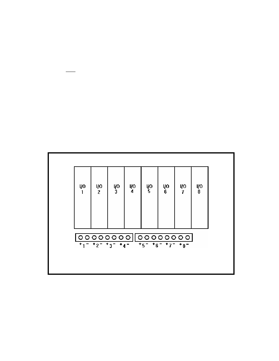
Step Five - Connect External Input/Output to the Dialer
Each I/O module
has two (2) corresponding I/O terminals. Channel 9 the power monitoring channel
doesn’t require external wiring. The expander cards are numbered 10 through 25 and 26
through 41 depending on their position and address. See Figure 9 & 10 below. Use 22
AWG shielded twisted pair wire when wiring external sensors to the I/O terminals.
Observe polarity when making connections. Whenever possible, ground the shield at the
sensor end only. Sensor control wires should never share conduit with AC power wiring.
NOTE: Keep I/O runs to a maximum length of 150 ft.
Refer to the Appendix for detailed field wiring diagrams, as well as electrical
specifications for each type of I/O Module you may install in the Series 1000EX. After
physical installation, each I/O module’s alarm operation must be configured. This is
covered in detail in the next chapter. The Quick Start procedure at the end of this chapter
provides information on a simple call-on-alarm configuration.
Figure 7. I/O Terminal Connections Channels 1 through 8
16