Sequence of operation, Flame safety controller pulley combination chart, Flame safety control – FloAire Compact Direct Fired Heater User Manual
Page 17: 7i n . bl ow e r, Pulley combination chart
17
Flame Safety Controller
Pulley Combination Chart
Motor RPM
1725
1/3 to 1-1/2 HP
MOTOR PULLEY
Dd1
Dd2
Pd1
Pd2
AX BELTS
1VP50
3.4
4.4
3.6
4.6
Open
Closed
BLOWER PULLEY
DATUM DIAMETER
PITCH DIAMETER
5
4 1/2
4
3 1/2
3
2 1/2
2
1 1/2
1
1/2
0
AK32H
3
3.2
1941
1995
2048
2102
2156
2210
2264
2318
2372
2426
2480
1/3 to 1-1/2 HP
MOTOR PULLEY
Dd1
Dd2
Pd1
Pd2
AX BELTS
1VL44
2.8
3.8
3
4
Open
Closed
BLOWER PULLEY
DATUM DIAMETER
PITCH DIAMETER
5
4 1/2
4
3 1/2
3
2 1/2
2
1 1/2
1
1/2
0
AK32H
3
3.2
1617
1671
1725
1779
1833
1887
1941
1995
2048
2102
2156
1/3 to 2 HP
MOTOR PULLEY
Dd1
Dd2
Pd1
Pd2
AX BELTS
1VL40
2.4
3.4
2.6
3.6
Open
Closed
BLOWER PULLEY
DATUM DIAMETER
PITCH DIAMETER
5
4 1/2
4
3 1/2
3
2 1/2
2
1 1/2
1
1/2
0
AK66
6.2
6.4
701
728
755
782
809
836
863
889
916
943
970
AK54
5
5.2
863
896
929
962
995
1028
1062
1095
1128
1161
1194
AK46
4.2
4.4
1019
1059
1098
1137
1176
1215
1255
1294
1333
1372
1411
AK39
3.5
3.7
1212
1259
1305
1352
1399
1445
1492
1539
1585
1632
1678
AK32
3
3.2
1402
1455
1509
1563
1617
1671
1725
1779
1833
1887
1941
TURNS ON MOTOR PULLEY
7
I
N
.
BL
OW
E
R
Pulley Combination Chart
TURNS ON MOTOR PULLEY
TURNS ON MOTOR PULLEY
Sequence of Operation
The direct-fired heater is most easily understood when broken down into smaller individual systems.
There are two main systems, a make-up air fan and a heater. The make-up air fan consists of a blower
and motor. The heater may be further broken down into two control systems, the Flame Safety Control
(FSC) and the Modulating Gas System (MGS). The burner mixes air with the gas (Natural or LP) which
heats the air.
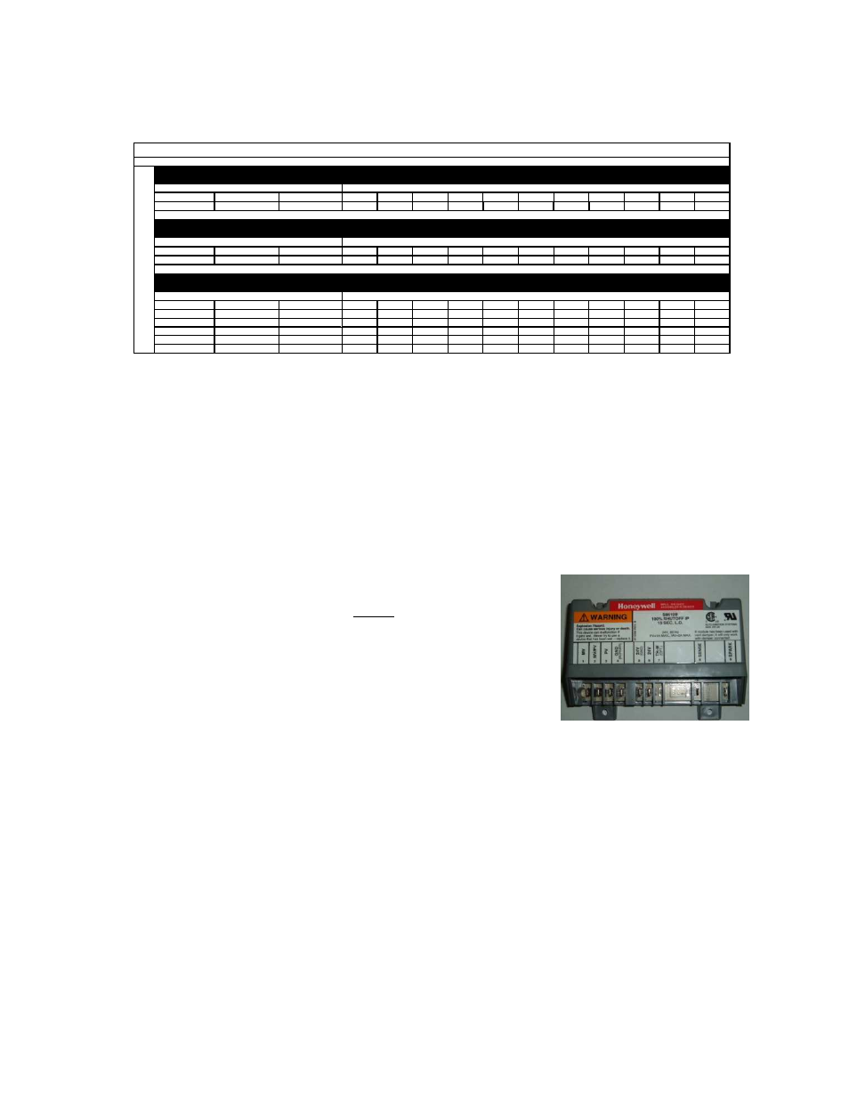
Flame Safety Control
The first system to understand is the Flame Safety
Control. The FSC
is there only to monitor the flame, NOT to control temperature. The
FSC uses a flame rectification sensor mounted on the pilot assembly
to detect the presence of flame in the burner. The FSC is also wired
into an airflow switch, which tells it whether there is proper airflow
through the unit (not just any airflow, but proper airflow). Proper airflow
occurs when there is a .15 in. w.c. to .80 in. w.c. differential
pressure drop across the burner. The FSC controls the opening of
the redundant solenoid gas valves and the operation of the spark
igniter to initiate a pilot flame upon start-up.
Upon a call for heat, there is a 15 second Pilot Trial For Ignition (PTFI).
During PTFI, the FSC opens the pilot gas valve and allows gas to flow
to the pilot assembly. At the same moment, the spark igniter is started,
causing the spark to ignite the pilot gas. When the flame rod sensor detects the flame it powers the
modulating gas system. This is the normal operating mode. The FSC continues to monitor the flame and
airflow. Once this occurs, the unit is in a main flame cycle and thus powers the main gas valve and the
modulating gas system. This is the normal operating mode. The FSC continues to monitor the flame and
airflow. If the flame fails to light after 15 seconds of sparking, the FSC goes in to lock-out mode. Anytime
this occurs, the problem must be diagnosed and corrected to avoid future lockouts after resetting. To
begin troubleshooting, or to reset the FSC, shut down power to the heater and restart the heater. This
will clear the alarm from the flame safety.