Remote sense enabled, Serial port 2, Remote sense disabled – Industrial Data Systems IDS 440 User Manual
Page 60: Serial port 1
IDS440 Users Manual version 4.2
56
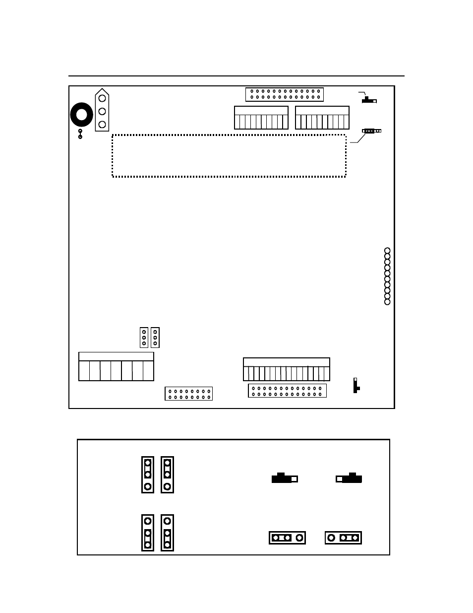
P.C. Board Diagram - Connectors, Jumpers, and Switches
Analog I/O connector
Power Supply Connector
TB4
Display
Keyboard Connector
Calibration Lock
Locked
Un-Locked
JP2
JP1
Remote Sense
Load Cell
1 2 3 4 5 6 7
SW2
Test / relay connector
Serial Port 2
1 2 34 5 67 8 9
Serial Port 1
1 23 4 5 67 8 9
JP4
TTL I/O
1 2 34 5 6 7 8 9
SW1
RS232
Com 1 input
JP3
Com 2 input
RS232
Remove
JP4 for
floating
ground
TB3
TB2
TB1
J2
J3
J4
J7
test connector
Remote Sense ENABLED
JP1
JP2
Serial Port 2
RS485 input
RS232 input
Remote Sense DISABLED
JP1
JP2
Serial Port 1
Current Loop in
RS232 input