Hardware and wiring – Industrial Data Systems IDS 440 User Manual
Page 57
IDS440 Users Manual version 4.2
53
Hardware and Wiring
This section describes installation and wiring information for the interface ports. There
are two bi-directional serial ports, one parallel port with TTL inputs and outputs, and one
load cell input port. The serial ports are used to interface to a printer and to a host device
or PC for continuous output. The parallel port is used to interface to parallel printers and
for remote switch input and relay control using the TTL I/O. The load cell input is used
to interface to the scale platform.
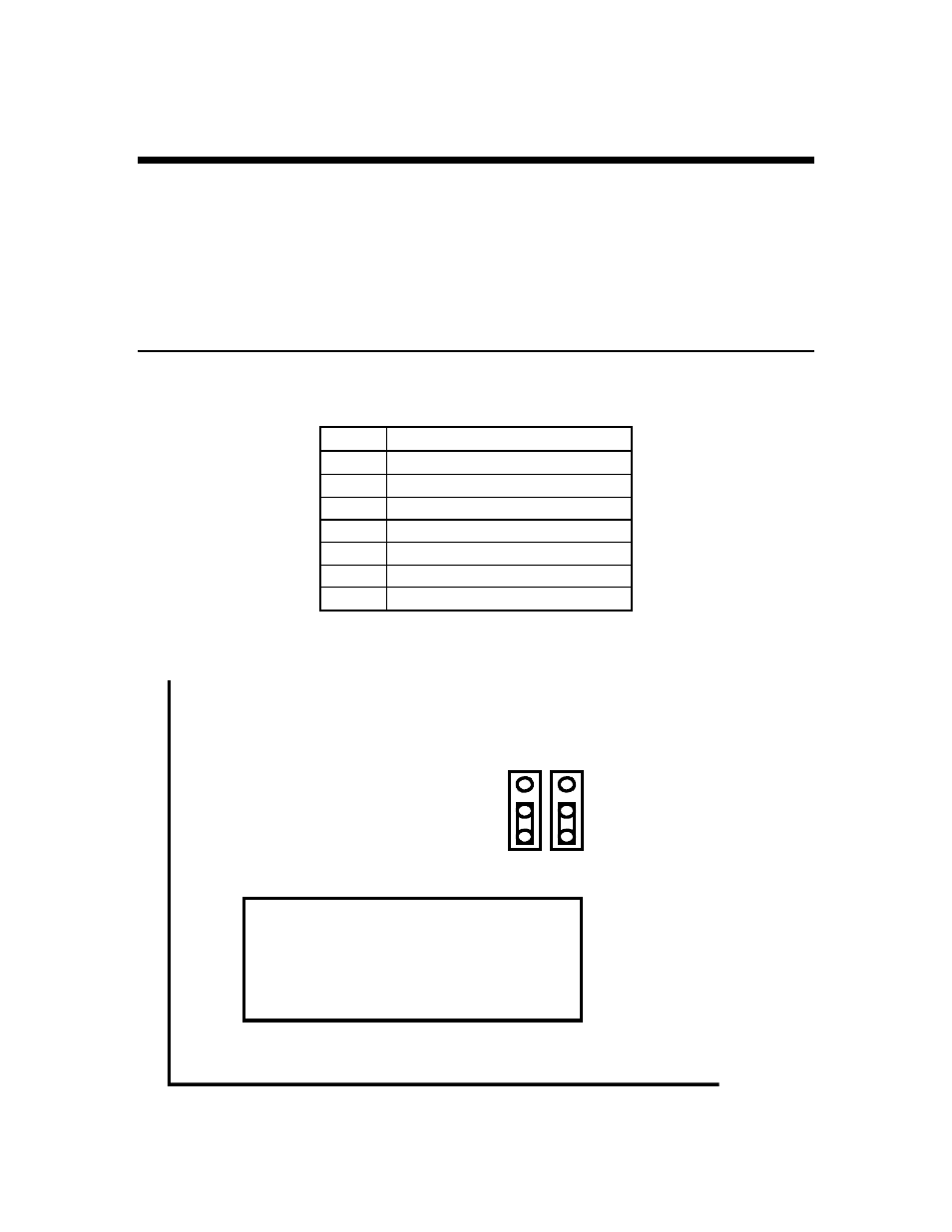
Load Cell Connector - TB3
NOTE: JP1 and JP2 on the circuit board can be used to disable remote sensing.
Load Cell - TB3
Pin # Signal Name
1
+ Signal
2
- Signal
3
+ Excitation
4
+ Sense
5
- Sense
6
- Excitation
7
Analog ground
JP1
JP2
TB3
Remote Sense Jumpers - Remote sense DISABLED
Load Cell Terminal Block
Place jumpers as shown to DISABLE remote sense. Move jumpers up to
enable remote sense.