Figure 4.4), Each set screw (figure – Wheatheart Self-Propelled Post Pounder Kit User Manual
Page 21
W
HEATHEART
- S
ELF
-P
ROPELLED
P
OST
P
OUNDER
K
IT
4. I
NSTALLATION
T
RAILER
P
OST
P
OUNDER
M
ODEL
4.2. W
HEEL
D
RIVES
IM12 R3
21
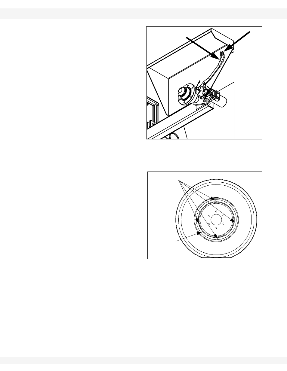
Note:
The hydraulic motors have 4
bolts that attach to each motor
mount. The 2 outer bolts must
be checked so they do not rub
against the ring gear. If they do,
the axle cap will need to be
moved back slightly toward the
frame. Ensure motor is oriented
as shown in Figure 4.3.
7. Double-check that pinion
gears and ring gears line up
properly. Remove wheels
and weld axle caps solid to
the spindles.
8. Lift
over-center
handle.
9. Line up chain locks to hold
each handle and weld in
place (Figure 4.3).
Note:
Removing wheels will make it easier to line up chain locks.
10. Weld the axle caps solid to
the frame.
11. Touch up paint and re-install
the over-center assemblies
and the wheels.
Figure 4.3
OVER-CENTER
HANDLE (LIFTED)
CHAIN LOCK
Figure 4.4
WELD 1” AT
EACH SET
SCREW
RING GEAR