Bird Technologies 429-83H-01 Series-Manual User Manual
Page 36
TX RX Systems Inc. Manual 7-9439-6 09/03/09 Page 28
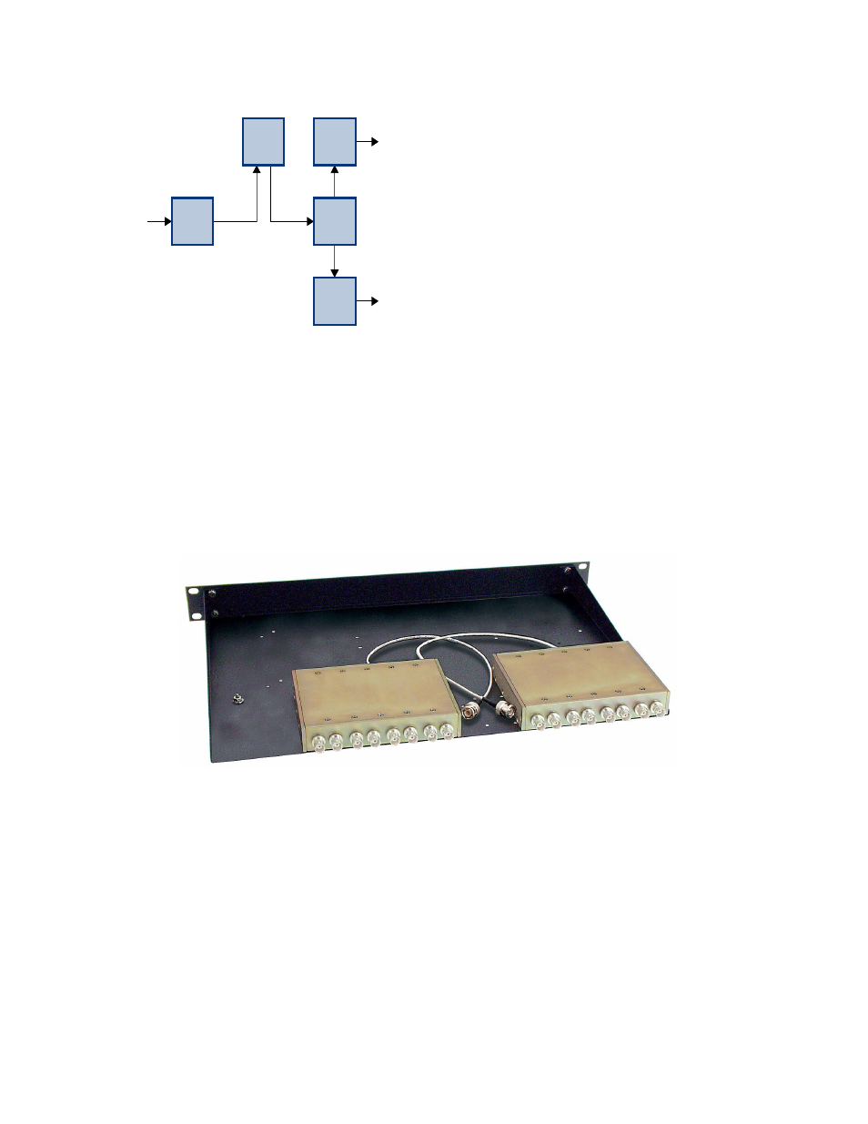
Figure 19 shows a basic interconnect diagram for
the filter, specific installation instructions are
included with the optional filter when it ships from
the factory. It is recommended that the filter be
mounted in the same rack just above the MCU.
The optional filter will require 2 “rack units” of
space.
Multicoupler Expansion Deck
The optional multicoupler expansion deck (part #
DDX1002A) is shown in Figure 20 and includes a
pair of 8-way dividers mounted on a 19 inch deck.
These 8-way dividers are designed to be con-
nected to the unused outputs of the 4-way divider
at the back of the MCU deck (refer to figure 2C).
With this option installed, a total of 32 system
receivers can be connected, with the system gain
remaining constant for all receivers. Cables are
provided for connecting the inputs of the 8-ways to
the unused outputs of the 4-way. It is recom-
mended that the multicoupler expansion deck be
mounted in the same rack just beneath the MCU
deck. The optional multicoupler expansion deck
will require 1 “rack unit” of space.
Figure 20: Optional multicoupler expansion deck, part # DDX1002A.
Dist
Amp
Opt
Filter
8-Way
4-Way
8-Way
RF
OUT
RF
OUT
RF IN
From
Tower
Figure 19: Optional filter interconnect diagram.