Bird Technologies 429-83H-01 Series-Manual User Manual
Page 13
TX RX Systems Inc. Manual 7-9439-6 09/03/09 Page 5
release the door. Make sure that all of the connec-
tors are tight. In addition, it is advisable to check
the tightness of the hold-down screws for the vari-
ous assemblies to insure nothing loosened during
shipment. Likewise, check all of the cable connec-
tions on the MCU to insure they are all properly
mated to their associated plugs.
CAUTION:
The wide band filter in
the tower top box is factory tuned
and must not be field adjusted. Field
tuning of this filter is not required. Do
not adjust the tuning slugs of the
amplifier/filter assembly.
Initial Power-Up Test
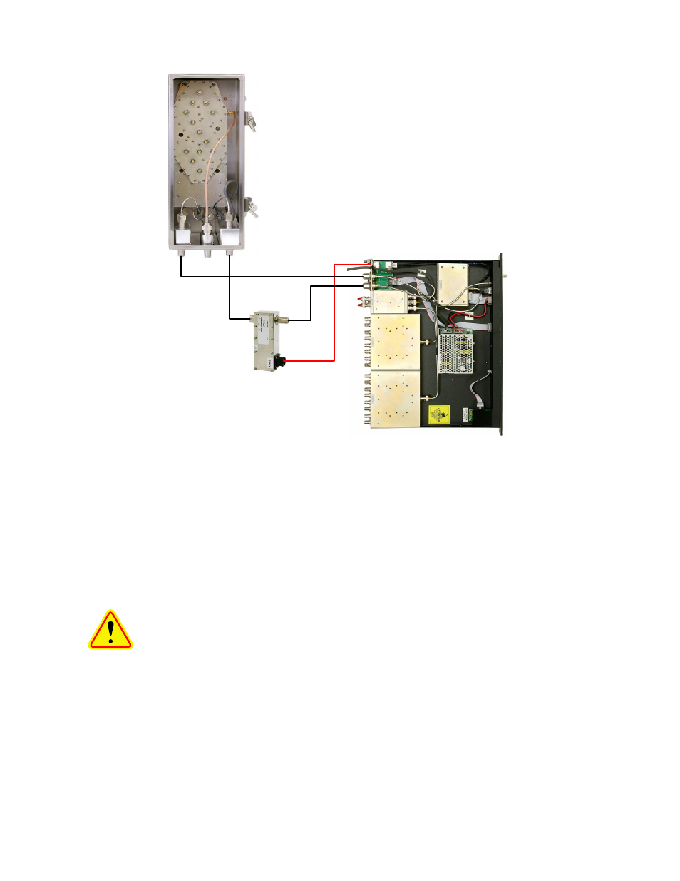
To perform the initial power-up test the system
should be temporarily interconnected at ground
level using short cables. Figure 4 shows the tem-
porary equipment hookup for initial power-up test-
ing.
Once the equipment is temporarily interconnected
then power is applied to the system by plugging the
MCU’s AC cord into a suitable AC outlet (model
429-83H-01-M) or connecting the DC power cable
to a suitable -48 VDC supply (model 429-83H-01-
M-48). The following start-up sequence occurs.
1) At turn-on, the three front panel status LED’s
will all glow a steady red while the display panel
shows a row of solid boxes on the top display
line. This will last for about 10 seconds while
the systems micro-controllers boot-up.
2) During the next 5 seconds the base unit (MCU)
will establish communications with the tower
box. The front panel status LED’s will occasion-
ally flash green. The display panel will present
the message “Connecting to Tower Controller”
and then will briefly flash the MCU’s current
software version. See Figure 5.
Tower Top Box
MCU
Lightning Arrester
TX RX part no. 8-21550
CAT-5e
Cable
Front
Panel
Test
Port
Test
Ant
Main
Figure 4: Initial power-up test.