INCRA Build-It STS Mortiser User Manual
Page 8
INCRA Build-It STS Mortiser Manual
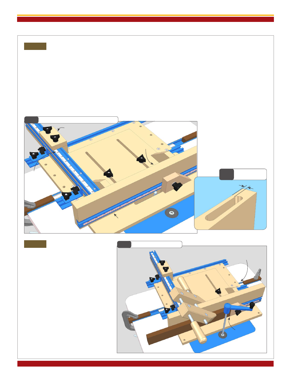
Set Distance from Edge of Slot to
Edge of Workpiece
You’ll first want to zero the faceplate to the edge of the cutter.
Loosen the clamping knobs that secure the faceplate assembly
and slide it forward to contact the cutting wing of the bit.
(You may need to rotate the cutter to find the “high spot”
of the cutting wing.) Hold the faceplate assembly steady as
you slide the T-Track fence stop positioner up to contact the
back of the faceplate assembly’s base and tighten the clamping
knobs. Note the position of the stop on the scale in the top
of the T-Track fence. (We suggest you slide the scale to read
at one of the whole inch numbers, or slide it to read at zero
if you don’t mind some of the scale hanging out of the end
of the fence.)
To set the cutter-to-faceplate distance, simply move the
T-Track stop positioner away from the back of the base
using the scale on the top of the T-Track fence as
a reference. Tighten the clamping knobs, then slide the
faceplate assembly back to contact the stop and tighten the
clamping knobs,
Fig. 24. For example, if we start with the
stop positioner set at 8” and
then move it to 8-
1
/
2
” along
with the faceplate assembly,
there should be
1
/
2
” between
the faceplate and cutter.
Page 7
Fig.24
Setting Slot to Board Edge Distance
Cutting the Slot
Now you can clamp your workpiece in
place and start the cutting process. Lower
the cutter until it is just flush with the top
of the Build-It throat plate. For horizontally
oriented material, place the board end
against the faceplate stop and clamp to
the faceplate.
Always begin and end
each cut with the jig against the
outfeed travel limit block. Turn on
the router and, using your router lift’s crank
handle, raise the cutter
1
/
16
” and slide the
jig between the two limit stops,
Fig. 25.
After each cut cycle, raise the cutter
1
/
16
”
until you reach the desired depth. You’ll
have to count the crank handle rotations
to keep up with how deep your cut is.
Fig.25
Cutting a Slot Mortise
Step 3
Step 4
Fig.23
Slot to Board
Edge Distance
3rd: slide faceplate assembly
to stop and clamp in place
T-Track
fence stop
2nd: using
scale as a reference,
slide stop away
by an amount equal
to desired slot-to-
edge distance
1st: slide faceplate to contact
cutter, then slide T-Track
fence stop to contact back
of faceplate assembly
ALWAYS begin and end each
cut with jig against the outfeed
travel limit stop block
clamp horizontal
material to
faceplate with
end against
faceplate stop