INCRA Build-It STS Mortiser User Manual
Page 5
INCRA Build-It STS Mortiser Manual
Page 4
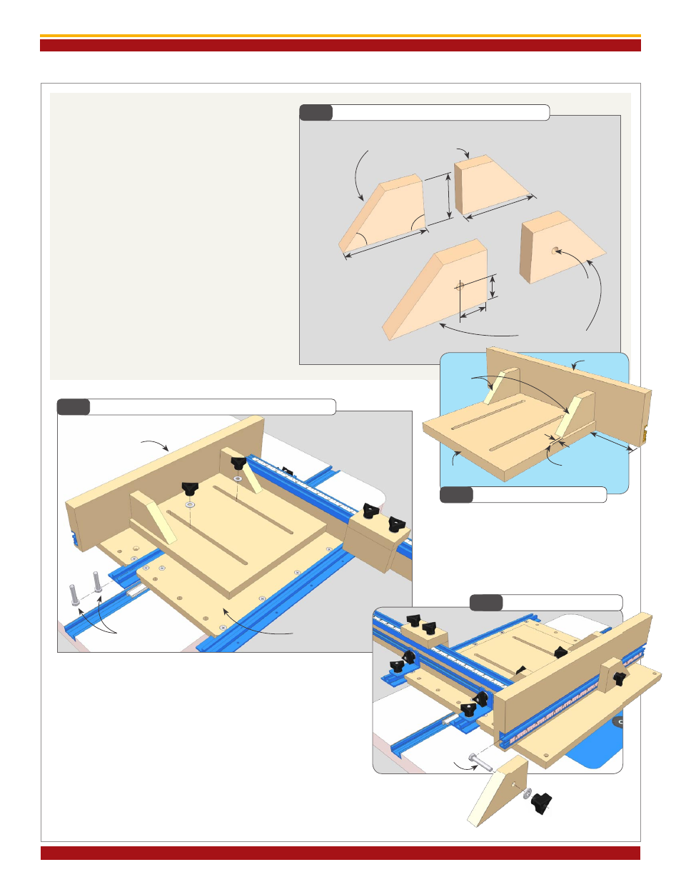
6. Cut the right angle supports and faceplate
stops to the dimensions shown in
Fig. 12.
All (4) pieces have identical dimensions.
Drill a
5
/
16
” diameter hole through (2) of the
pieces and set aside for later use as faceplate
stops.
Glue up the right angle faceplate assembly, placing
the right angle supports about
1
/
4
” away from
the edge of the base,
Fig 13.
Fig.12
Right Angle Supports and Faceplate Stops
Fig.14
Attach Faceplate Assembly to Build-It Platform
7. Secure the right angle faceplate assembly to your Build-It
Platform using (2)
1
/
4
-20 x 1-
1
/
2
” hex bolts with washers and
clamping knobs as shown in
Fig. 14.
Slide the slotted base of the faceplate assembly up to the T-
Track Fence and tighten the clamping knobs. Attach the (2)
faceplate stops to the assembly using (2)
1
/
4
-20 x 1-
1
/
2
” hex
bolts with washers and clamping knobs,
Fig 15.
Fig.13
Glue Faceplate Assembly
Fig.15
Attach Faceplate Stops
5
/
16
” dia
hole (2)
4”
4”
2
1
/
4
”
right angle supports
1
1
/
8
”
1
1
/
8
”
faceplate stops
4”
1
/
4
” approx.
base
right
angle
support
faceplate
faceplate
assembly
1
/
4
”-20 x 1
1
/
2
”
hex bolts
Build-It Platform
45°
90°
1
/
4
”-20 x 1
1
/
2
”
hex bolts