Alicat P Series Pressure Gauge User Manual
Page 33
33
PCD-SERIES DUAL VALVE PRESSURE CONTROLLER OPERATION
Alicat Scientific PCD-Series Closed Volume Pressure Controllers incorporate a
digital pressure gauge with dual control valves and circuitry. The integrated PID
loop measures the pressure, compares it with the set-point, and adjusts either
the Inlet or Exhaust valve accordingly in excess of two thousand times per second.
It is most common to have a .050 inch diameter orifice in the inlet valve, and
a .050 inch diameter exhaust valve. The response time of the system will
depend on the size of the volume being controlled and the feed pressure. The
controllers are intended for use with clean, non-corrosive gases only.
They are designed with a feed port, a process port, and an exhaust port. This
allows the controllers to raise and lower the pressure of a closed system within
the operating range of the controller without wasting gas under constant
pressure conditions.
Plumbing
Connect your PCD into your process via the 1/8” NPT port on the front of the
unit. This is the “Process” port.
Connect a supply pressure greater than the full scale pressure control range of
the device, not to exceed 145 psig, to the inlet 1/8” NPT port on the left side
device. This is the “Inlet” port.
The 1/8” NPT “Exhaust” port, located on the right side of the device can vent to
atmosphere if the application is suitable, or to a collection network if necessary.
The pressure at the exhaust port should be at atmospheric pressure or below to
allow the controller to be used over its full scale range.
If desired, there are two 8-32 mounting holes located on the bottom of the unit
as shown in the dimensional drawing on page 52.
Connect your PCD to power and output lines as detailed on pages 9 - 12.
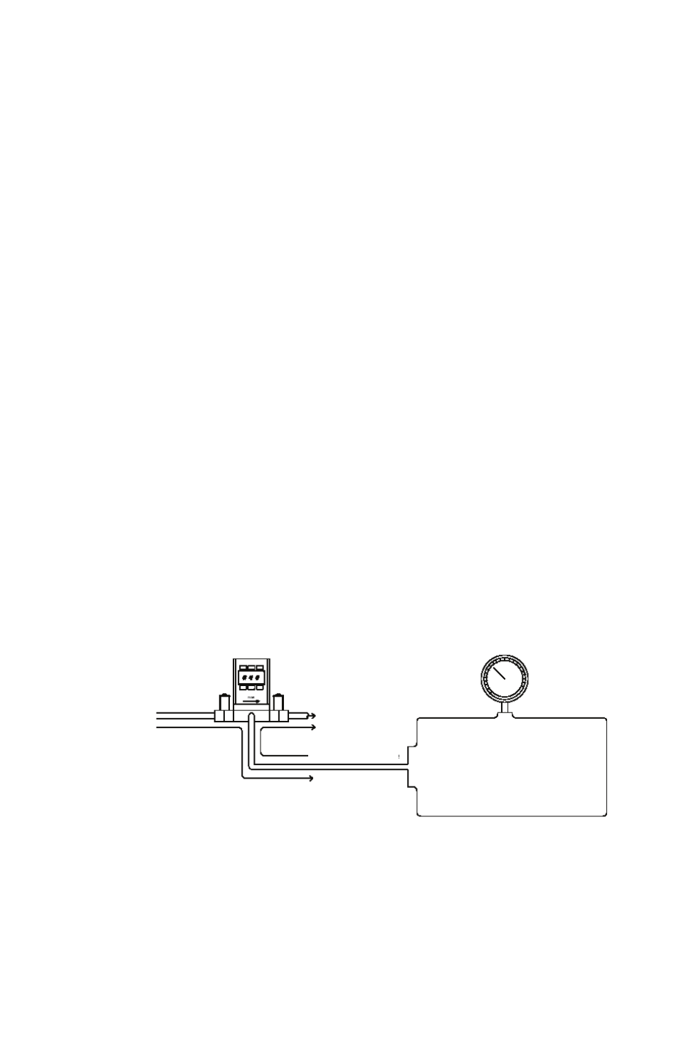
Supply Pressure
Closed Volume
Decrease Pressure
Exhaust
Increase Pressure
Typical PCD Plumbing Diagram