6 continuous warm system, 1 setting-up the monitor to continuous warm system, Select general set-up branch ? clock sound tests – LumaSense Technologies INNOVA 1412i User Manual
Page 70
Chapter 5
______________________________________________________________________
_____________________________________________________________________________
BE6025-15
1412i Photoacoustic Gas Monitor
LumaSense Technologies A/S
Page 70 of 202
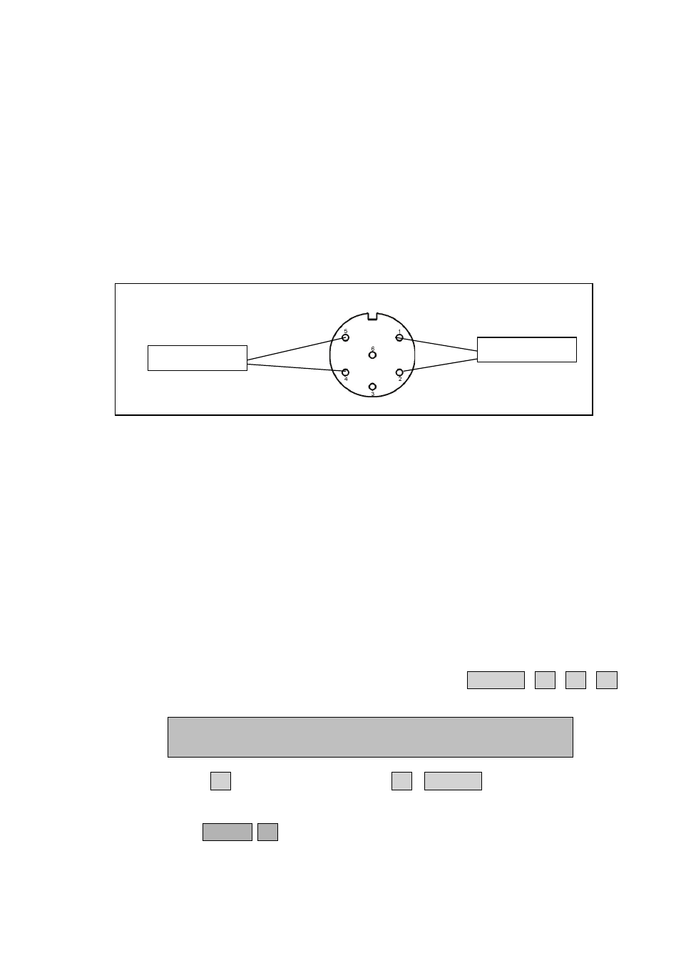
LumaSense supplies a 6-pin DIN plug (male) with a locking collar
JP0600 for connecting external alarm devices to the alarm relay.
Caution:
The DC voltage across the relay contacts must not exceed 25V. The
potential on the relay contacts must not be more than 25VDC above
chassis potential, as this will cause an excessive leakage current. The
current through the contacts must not exceed 100mA. AC voltages
must not be connected to the Alarm Relay socket.
Fig.5.2 Configuration of the pins in the alarm relay socket
5.6 Continuous Warm System
The Continuous Warm System ensures that the monitor is kept warm
at any time that is also when the Monitor is not measuring.
If the Monitor is powered up at all time you can save the warm up
time when starting a measurement.
5.6.1
Setting-up the Monitor to Continuous Warm System
The procedure to enable the Continuous Warm System is as follows:
1. Press the following push-button sequence: SET-UP S3 S1 S1,
and the following text is displayed:
2. Press S3 q three times S3 SET-UP. This selects the
continuous warm system.
3. Press RESET S1 (Partial Reset) in order to enable the continuous
warm system.
SELECT GENERAL SET-UP BRANCH ?
CLOCK SOUND TESTS
Alarm relay 1
Alarm Relay 2