LumaSense Technologies INNOVA 1412i User Manual
Page 103
Chapter 9
______________________________________________________________________
_____________________________________________________________________________
BE6025-15
1412i Photoacoustic Gas Monitor
LumaSense Technologies A/S
Page 103 of 202
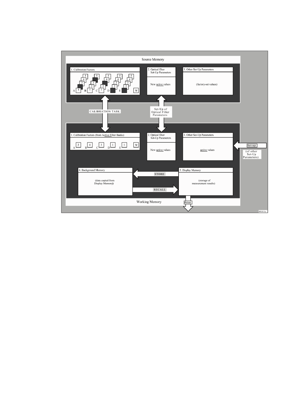
Fig.9.1 Schematic diagram showing the structure of the Monitor’s
memory
Before calibrating a particular filter, one of the filter’s banks is made
active (by operating the Monitor in Set-Up mode and “entering” the
chosen filter-bank number for the filter being calibrated). The filter
bank No. which is made active before the filter is calibrated, is the
filter bank where the Monitor will store calibration factors calculated
during calibration. This means that the user is able to calibrate any
particular optical filter to measure up to five different gases.
If a particular filter is to measure more than one gas, it is therefore
necessary to span calibrate it with each of the gases it is to
measure. For example, if you refer to the “Gas Detection Limits”
wall chart you will see that the filter UA 0976 can be used to meas-
ure the following three gases:
1. Sulphur hexafluoride
2. Acetic acid
3. Vinyl chloride
Suppose that filter UA 0976 is installed in position “A” of the filter
carousel to measure each of the above gases. Before this filter is
calibrated, the Monitor has to be told where to store the calibration