Sensor tests – GxT Ferret 91 2-Channel Labscope User Manual
Page 12
12
Sensor Tests
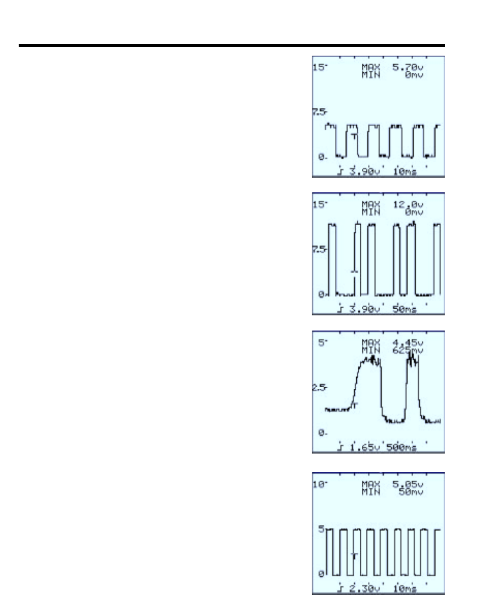
Hall Effect VSS
Connect COM probe to the sensor’s ground circuit, engine
block, or negative battery post. Connect CH1 probe to
the crankshaft sensor’s signal circuit to the PCM. Connect
CH1 probe to the sensor signal circuit to the PCM. As the
wheels begin to spin, digital pulses should increase in
frequency as wheel speed increases. Check the waveform
for proper shape, frequency, and amplitude.
Optical VSS
Connect COM probe to the sensor’s ground circuit, engine
block, or negative battery post. Connect CH1 probe to
the crankshaft sensor’s signal circuit to the PCM. Connect
CH1 probe to the sensor’s signal circuit to the PCM. Crank
or start the engine, let the engine idle, rev the engine, or
drive the vehicle to make the driveability or emissions
problem occur. Check the waveform for proper amplitude
at any given engine vacuum.
Analog MAP Sensor
Connect COM probe to the sensor’s ground circuit, engine
block, or negative battery post. Connect the CH1 probe
to the camshaft sensors’ “high”, “+”, or signal output to
the PCM or ignition control unit. Crank or start the engine.
Let the engine idle, rev the engine, or drive the vehicle to
make the driveability or emissions problem occur. Check
the waveform for proper shape, frequency, and amplitude.
Digital (Ford) MAP
Connect COM probe to the sensor’s ground circuit, engine
block, or negative battery post. Connect the CH1 probe
to the camshaft sensors’ “high”, “+”, or signal output to
the PCM or ignition control unit. Crank or start the engine.
Let the engine idle, rev the engine, or drive the vehicle to
make the driveability or emissions problem occur. Check
the waveform for proper shape, frequency, and amplitude.