Gardner Bender B400 Series Eegor Hydraulic Benders User Manual
Page 9
9
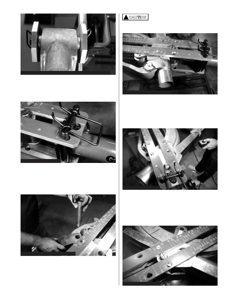
5. Install the double anchor pin (BZ74) through the
two holes marked “Start” 3
1
⁄
2
"–4". Both legs of the
pin must extend through the top frame, the
cylinder block and through the lower frame.
Figure 30.
6. The “U” strap attaches to the bending shoe by
first placing the strap over the shoe, then inserting
the strap retaining pin (BZ76). Be sure the conduit
size number is facing up and the retaining pin is
protruding through the bottom of the “U” strap.
Figure 31.
Figure 29: Upper Frame Shoe & Lower Frame Pinned Together
Figure 30: BZ74 Installation
Figure 31: “U” Strap & Pin Installation
To avoid damaging the follow bar, rest
it against the “U” strap. Do not attempt
to bend conduit if a gap exists
between the follow bar and “U” strap.
Figure 32: Follow Bar Installation
!
CAUTION
8. Turn pump on. Press the pendant button to
“Advance”. Push on the rear of the follow bar until the
conduit and follow bar begin traveling through the
rollers. Figure 33.
NOTE: Consult older instructions for Eegor
®
models
without bend angle decal on frame.
Figure 33: Begin Bending
7. Slide conduit into the shoe groove until it enters
the “U” strap and protrudes a minimum of 2"
beyond the “U” strap. The mark placed on the
conduit must be visible at the outer edge of the “U”
strap. Slide the follow bar (tapered end first)
between the conduit and roller assembly.
Figure 34: Angle Indicator
9. To determine bend angles, watch the scribed
marks on the roller shaft as it travels past the white
numbers on the red decal. The decal is marked for
all angles and for IMC, Rigid, and EMT conduit.
Locate your specific angle and conduit type on the
decal. When the roller shaft reaches the angle you
desire, release the pendant button.