Bending conduit – Gardner Bender B400 Series Eegor Hydraulic Benders User Manual
Page 7
7
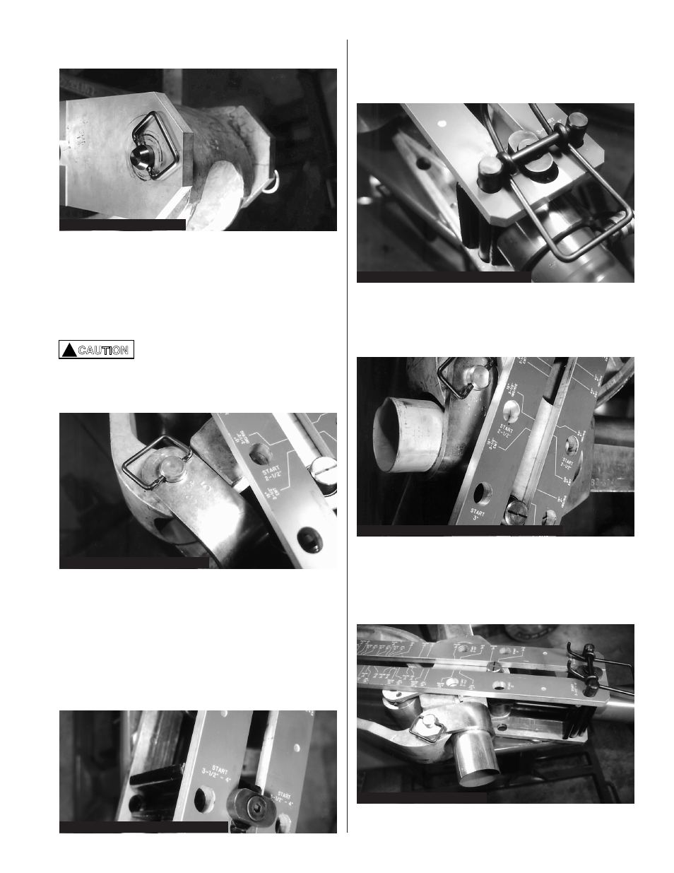
Figure 20: Install Frame & Pin
Figure 21: “U” Strap & Pin Installed
Bending Conduit
A. B400 and B400D
1. The cylinder mounting block has a groove along
each side to accept the double anchor pin. Move
the hydraulic cylinder until the grooves in the
mounting block are aligned with holes in the
frame. The numbers next to the holes must agree
with the conduit size being bent. Figure 22.
Figure 22: Start Holes for Conduit Sizes
2. Install the double anchor pin (BZ74) by inserting it
in the holes of the upper frame, through the block
grooves and through the holes of the lower frame.
Figure 23.
8. Turn locking pivot on cylinder block until it is
positioned across the slot in the frame.
9. Place the “U” strap on the end of the bend shoe.
Be sure the number, stamped in the strap, is
facing up. Secure with “U” strap pin BZ76.
Figure 21.
The “U” strap pin (BZ76) must be
through the top hole, bend shoe and
bottom hole of “U” strap. If the bottom
hole is not engaged, the “U” strap will
be damaged during bending.
Figure 23: Double Anchor Pin Installation
!
CAUTION
Figure 24: Installing Conduit in Shoe & “U” Strap
3. Slide conduit into the shoe groove and through the
“U” strap. At least 2-3 inches of conduit must
extend beyond the “U” strap to avoid deforming
the end of the conduit. Figure 24.
4. Insert the correct follow bar, tapered end first,
between the rollers and conduit. The follow bar
must be firmly seated against the “U” strap. A
follow bar is used for all types of conduit.
Figure 25.
7. Position the upper frame over the shoe assembly.
Align the single pivot hole with the pivot hole in the
Figure 25: Follow Bar Installed