Gardner Bender B400 Series Eegor Hydraulic Benders User Manual
Page 5
5
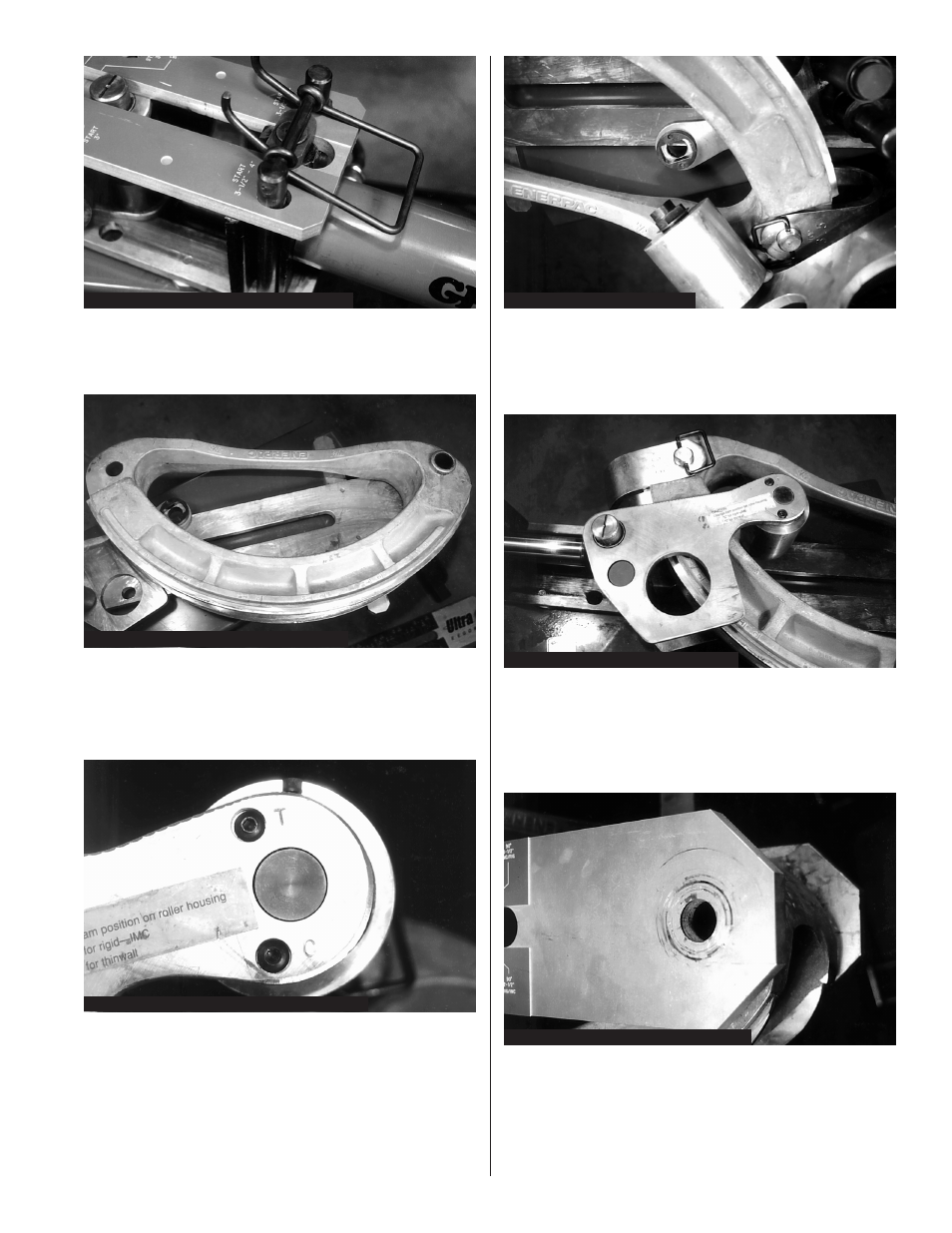
2. Position the desired size shoe on top of the lower
roller and plate assembly. Be sure the bend angle
numbers are facing up. Figure 9.
Figure 8: Locating B400L Hydraulic Cylinder
Figure 9: Positioning Bend Shoes on B400L
3. The top plate and roller assembly is installed over
the shoe. Prior to installation, move the indicator
knob to the “C” position for rigid or IMC conduit;
the “T” position for EMT (thinwall). Figure 10.
4. The large roller axle has two flats which engage
the retaining collar on the lower plate. Press the
upper plate down until the lower roller axles are
flush with the top plate holes and the flats of
the upper roller shaft are firmly seated in the
retaining collar.
Figure 10: Position Indicator Knob to “C” or “T”
Figure 11: Top Plate Installation
NOTE: The roller assembly axle may not engage the
collar initially. To ensure proper engagement,
move the indicator knob slightly until the axle
seats properly. Figure 12.
Figure 12: Correct Upper Plate Position
Figure 13: Hole Alignment Pivot Pin BZ78
5. Move the bend shoe to align the pivot hole with
the hole in the bottom frame. If the shoe is too far
away, start the hydraulic pump. Advance the
cylinder until the pivot hole is located under the
frame hole. Install the pivot pin (BZ78). Figure 13.
6. Install the “U” strap. Be sure the U-strap size
matches the bend shoe size. The stamped
numbers must face up. Position the “U” strap and
secure with pin BZ76. Figure 14.