Bender assembly – Gardner Bender B400 Series Eegor Hydraulic Benders User Manual
Page 3
3
The Eegor
®
bender develops 30 tons of force at 9,250
psi. Greater forces will be generated between the
rollers, follow bars and bending shoe. Operators must
follow instructions for assembly and bending conduit
to avoid pinch points and applying forces to incorrect
bender components.
Do not use damaged parts to assemble the
Eegor
®
bender. Items that are damaged or broken
due to extensive wear must be replaced to avoid
potential hazards to the operator.
Keep hands and loose clothing away from all moving
parts. Frames and rollers move under high pressure.
Do not place hands on conduit or between conduit
and follow bar during operation. Severe injuries could
result.
Do not connect or disconnect hydraulic hose fittings
with pressure in the system. A rigid hose indicates the
presence of internal pressure. Prior to electrical or
hydraulic repairs, retract the hydraulic cylinder and
turn off the hydraulic pump.
!
CAUTION
!
CAUTION
!
WARNING
!
CAUTION
IMPORTANT—USER SAFETY AND PROTECTION: In setting up systems, take care to select the proper
components and design to ensure appropriate integration with your existing operations and equipment. Observe all
safety measures to avoid the risk of personal injury and damage to property and equipment through improper usage.
Bender Assembly
A. Frame Assembly
1. Remove the frame assembly and hydraulic
cylinder from the metal case. Place the assembly
on a flat surface. Figure 1.
The cylinder slides within the frame
assembly. When lifting or moving,
keep the frames as level as possible
to prevent injury from moving parts.
!
CAUTION
Figure 1: Frame Assembly
Figure 2: Lock-on Frame
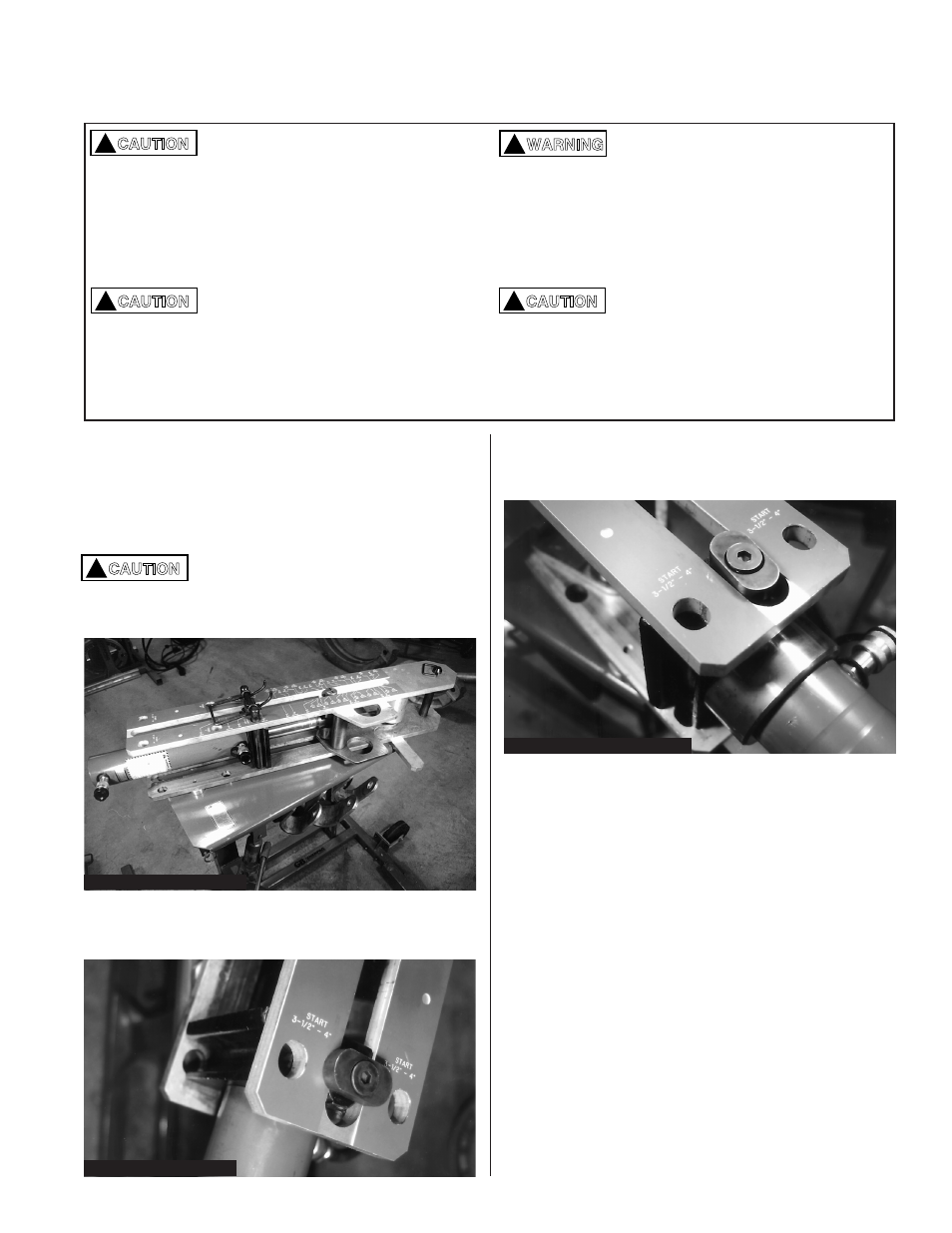
2. A pivoting lock holds the top frame in place.
Figure 2.
3. Turn the pivot lock to align it with the slot in the
frame. Lift the top frame off the roller assembly.
Figure 3.
Figure 3: Removing Top Frame
4. Place your foot on the lower frame, grasp the end
of the hydraulic cylinder and pull it toward you.
Align the slots of the cylinder mounting block with
holes in the lower frame that correspond with
conduit size being bent. Figure 4.
NOTE: For model B400L and B400DL align the
cylinder block with the holes for 3
1
⁄
2
" & 4"
conduit size (last holes in frame).
The
cylinder will remain in this position for all
bending sizes and angles to 90˚.