Bending shoe and follow bar installation – Gardner Bender B400 Series Eegor Hydraulic Benders User Manual
Page 4
4
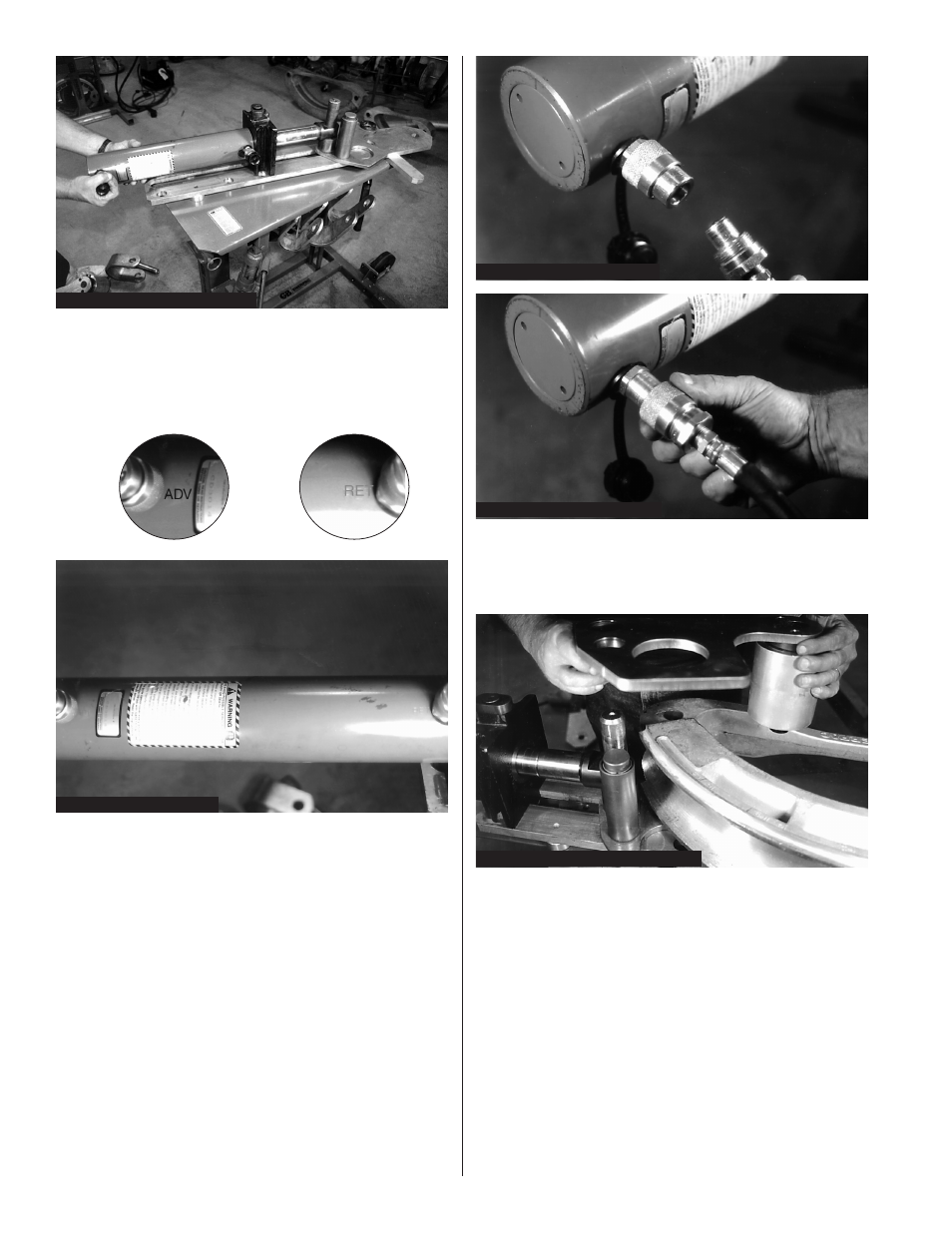
7. Remove the upper roller and plate assembly by
pulling straight up. The upper plate and large
aluminum roller are a single assembly. Figure 7.
Figure 5: Hose Installation
Figure 6A: Installing Couplers
Figure 7: Upper Roller Plate Removal
Figure 6B: Installing Couplers
Figure 4: Moving Cylinder Frame
5. Install the two hydraulic hoses. Apply one wrap of
teflon tape to the threads on the end of the hose.
Remove the pipe plugs from the pump valve, one
port is marked “ADV” the other is marked “RET”.
Install a hose in each port. Figure 5.
6. Connect the hose from the “ADV” port to the
hydraulic cylinder coupler located near the base
of the cylinder. Make sure there is no dirt or
debris in either half prior to assembly. Push the
hose coupler firmly into the cylinder coupler, then
tighten coupler collar. Connect the hose from the
“RET” port to the remaining cylinder coupler.
Figure 6A & 6B.
IMPORTANT: The hose coupler must be firmly
seated in the cylinder coupler and held
tightly while turning the coupler collar.
Hand tighten the collar.
Do not use
tools to tighten. Failure to properly
assemble couplers will inhibit oil flow.
8. The lower plate and roller assembly remain
in position during normal shoe and follow
bar installation.
Bending Shoe and
Follow Bar Installation
A. Model B400L and Model B400DL Ultra Eegor™
1. The B400L and B400DL use a 28" hydraulic
cylinder. As a result, the upper and lower plate
assemblies use the 3
1
⁄
2
"–4" frame holes for
mounting all sizes of conduit bending shoes. See
figure 8. For smaller sizes of conduit, the cylinder
plunger must be advanced to position the roller
assembly against the follow bar.