Installing vent pipe, Warning – Hearth and Home Technologies Cinch Pipe & Termination Cap System User Manual
Page 5
Hearth & Home Technologies Inc. • Cinch Pipe & Term Caps • 4033-900 Rev K • 05/05
5
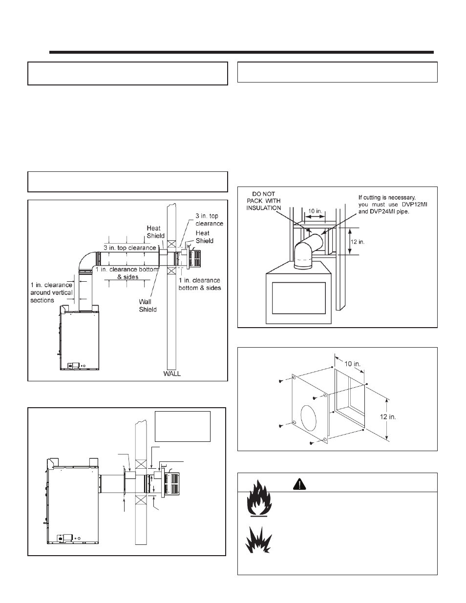
3 in. (76 mm)
top clearance
1 in. (25 mm)
clearance
bottom & sides
Heat
Shield
Wall
Shield
Heat
Shield
WALL
Note: Heat shields
MUST overlap by a
minimum of
1-1/2 in. (38 mm).
Figure 2.2
Horizontal Venting Clearances to Combustible Materi-
als - Rear Vent
A. Clearances for the Vent Sections
•
Top Vented Direct Vent Appliances
For all top vented, direct vent appliances, clearances to
combustible materials from the venting system need to
be maintained as shown in Figure 2.1.
• Rear Vented Direct Vent Appliances
See Figure 2.2.
Figure 2.1
Horizontal Venting Clearances to Combustible Materi-
als - Top Vent
Note:
For termination cap installations only, go directly to Sec-
tion E.
Note:
Refer to the appliance installation instructions for al-
lowed vent lengths and confi gurations.
2
Installing Vent Pipe
B. Penetrating a Wall
Wherever a combustible wall is penetrated, the hole must
be framed with an interior wall shield (DVP-WS) as shown in
Figures 2.3-2.4. This shield maintains minimum clearances
and restricts cold air infi ltration. If the wall being penetrated is
of noncombustible materials (material which will not ignite or
burn, or has a UL fi re rating of zero), a 9 in. diameter hole is
acceptable. Whenever a wall is penetrated the wall shield is only
required on one side and no heat shield is necessary. If your
local inspector requires the wall shield on both sides, then both
wall shields must have a heat shield attached to them.
Figure 2.4
Interior Wall Shield
Figure 2.3
Exterior Wall Hole
Note:
Heat shields MUST overlap by 1-1/2 in. min. for rear
vented appliances.
Fire Risk
Explosion Risk
Maintain vent clearance to combustibles as
specifi ed.
• Do not pack air space with insulation or
other materials.
Failure to keep insulation or other materials
away from vent pipe may cause fi re.
WARNING