Mounting hole layout, Mounting hole layout , pa – HP 288048 User Manual
Page 28
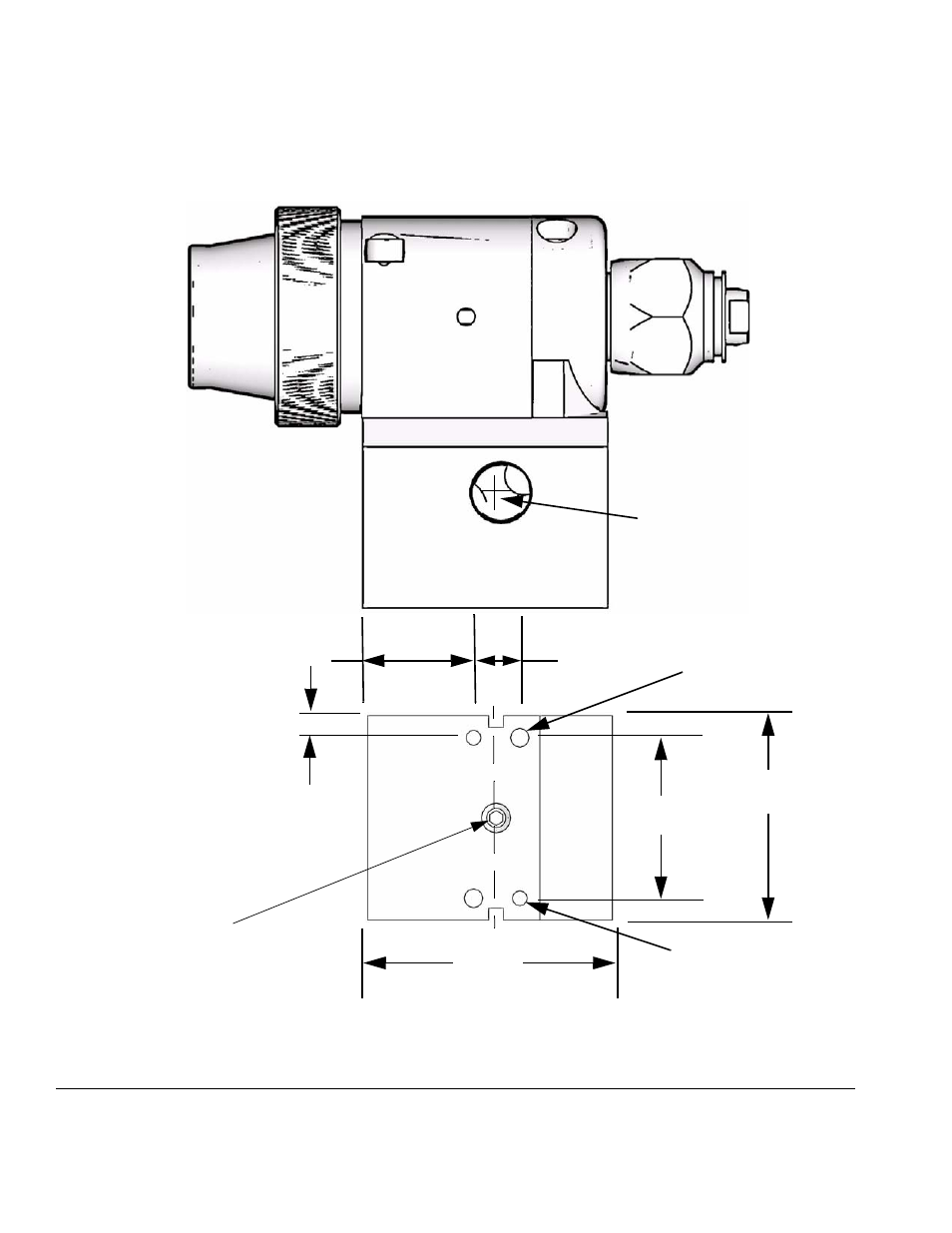
Mounting Hole Layout
28
311053C
Mounting Hole Layout
F
IG
. 20: Manifold Mounting Hole Layout
0.4 in.
Two M5 x 0.8 x 0.25 in.
0.805 in. (20.5 mm)
0.187 in. (4.8 mm)
1.375 in.
(35 mm)
Two 0.128 diameter x
0.31 in. (7.8 mm) deep
2.125 in.
(54 mm)
holes (for alignment pin)
Remove set screws
when using bottom
mounting pattern.
(6.3 mm) holes
1.750 in.
(44.5 mm)
TI8116a
TI8107a
0.5 in.
(12.7 mm)
See also other documents in the category HP Tools:
- LSGX203M (39 pages)
- A3312AZ (149 pages)
- R5500 (61 pages)
- R1500 (49 pages)
- PROCURVE 2610 (112 pages)
- COMBI 2180206H (36 pages)
- A1354A (120 pages)
- Power Management System (32 pages)
- Power Management (27 pages)
- C4788x (37 pages)
- 6621A (115 pages)
- 6631B (75 pages)
- Anab EQ Series (131 pages)
- T2200 (55 pages)
- T1500 (48 pages)
- Aikido Stereo 9-Pin PCB (13 pages)
- GRACO OR PRO TI1681A (70 pages)
- GMAX 5900 (28 pages)
- Teco MA7200 Plus (12 pages)
- R2200 (61 pages)
- 4445-95 (5 pages)
- 32A (7 pages)
- AUTOMATIC XT SPAY GUNS 311051D (38 pages)
- X09 (54 pages)
- R12000 XR (69 pages)
- Paslode 403606-10 (15 pages)
- Extech 380976 (20 pages)
- XLWW (10 pages)
- T2200 XR (51 pages)
- SCSI (48 pages)
- 39-1572 (10 pages)
- 2995 (20 pages)
- Insight Control (60 pages)
- Insight Control (64 pages)
- Software HP Matrix Operating Environment (65 pages)
- Insight Control (60 pages)
- Insight Control (45 pages)
- Insight Control (73 pages)
- Insight Control (87 pages)
- Insight Control (18 pages)
- Insight Control (24 pages)
- Insight Control (79 pages)
- Insight Control (85 pages)
- Insight Control (43 pages)