Specifications, Hubbell offers, Hubbell – Hubbell Microprocessor Radio Locomotive Control 31200 User Manual
Page 3
HUBBELL
Specifications
Supply Voltage ......................... 12VDC, 24VDC, 36VDC or 72VDC
Internal Power Requirements ........ +11.9–13.1VDC & +4.5–6.5VDC
Operating Temperature .............. –22°F (–30°C) to 140°F (+60°C)
Radio Receiver
Frequency Range ...................... 72–76 MHz or 450–470 MHz
Channel Availability .................. as required by user
Frequency Stability .................... ±5 ppm
Sensitivity ................................ 1 µv @ 20 dB quieting
Data Reception ......................... compatible with existing transmitters
Modulation .............................. biphase
Baud Rate ............................... 4800 bps
Message Format ....................... preamble, sync pattern, start flag, address, control, CRC
check code
Control Section
Single board computer consisting of 80C31BH controller, 64k EPROM, EPLD containing cir-
cuits for message synchronizing, and processor watchdog
Switches ................................. 8 position address dip, 4 position message timer dip
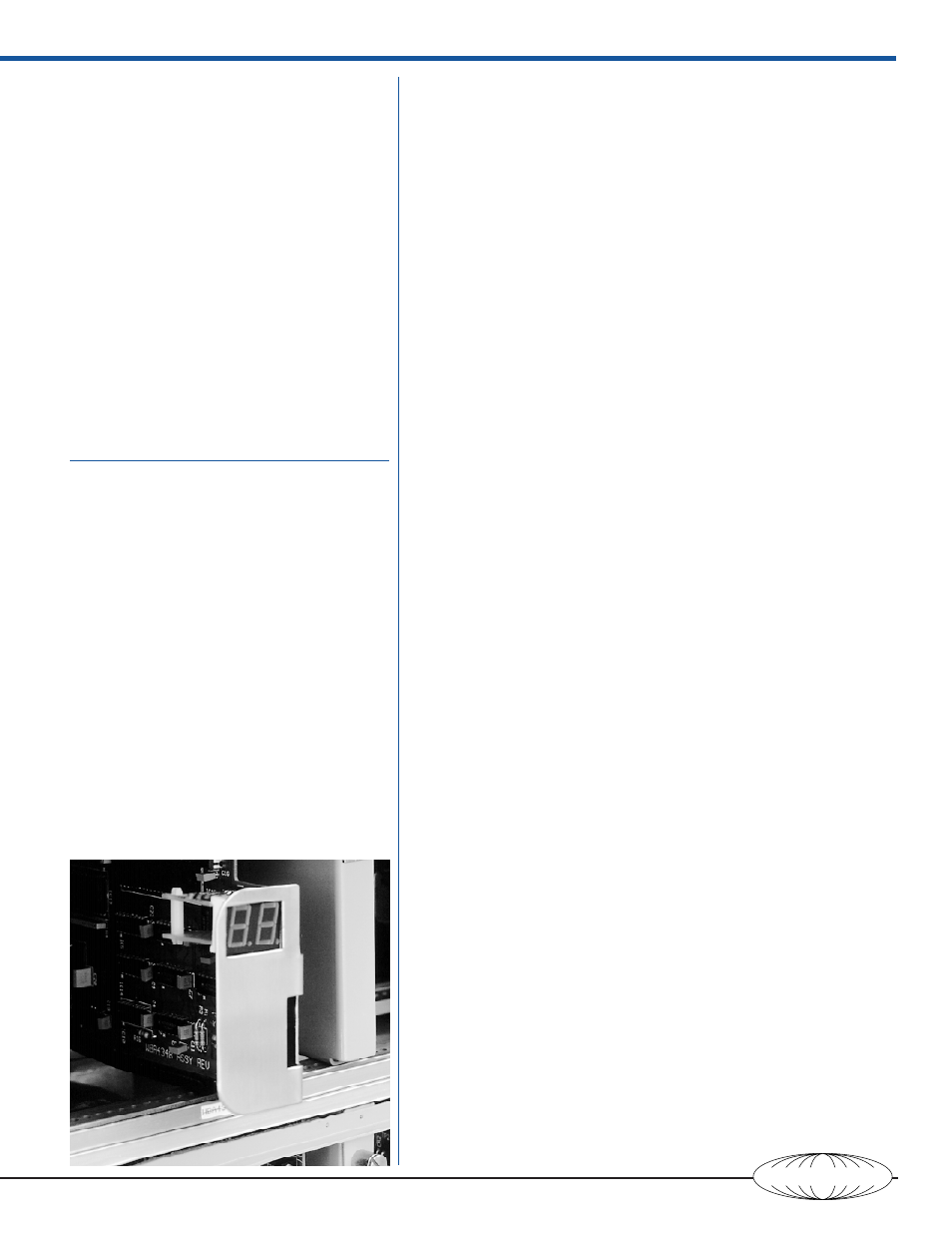
Indicators ................................ 2 digit display (7 segment LED) for self diagnostics & error
conditions
Firmware ................................. written in 8031 assembly language structured for ease of
customization of output control
Functions ................................. message input address decoding, error checking, control
bit decoding, output control self diagnosis
Paralleled I/O ......................... basic system uses single board, up to three additional
boards may be added
Output per board ...................... 48 software programmable for input or output with
readback on all outputs
Driver per output ....................... TTL compatible for up to 25mA sink
DC Output Section
Solid state relay PC boards in card cage.
Type ....................................... Opto Isolated
Indicators ................................ Red: output activated
Output Voltage ......................... 24VDC
Input Voltage ............................ 4.5–6.5Vdc, active high
Load ....................................... 0.5A, 24VDC, inductive
Isolation .................................. 1500V
Input Board
Input 24 VDC sensing PC board in card cage.
Indicator ................................. Red: input activated
Input ....................................... 24VDC nominal
Isolation .................................. 1500V input to output & between circuits
Output .................................... Opto-isolated; active low
comotive magnetics and
pneumatic systems in re-
sponse to decoded control
commands. The configura-
tion of the manual control
switches is duplicated and
wired to industrially rated
terminals for interconnec-
tion to the locomotive con-
trols. A manual-remote
transfer switch is provided
to completely isolate the
radio system from the man-
ual controllers.
The receiver antenna is
normally mounted on the
locomotive cab, and suffi-
cient co-axial cable is pro-
vided to connect the an-
tenna to the radio receiver
module in the cabinet.
Pneumatic Cabinet
The pneumatics enclosure
is of NEMA 12 construc-
tion and houses the pneu-
matic controls for the re-
mote operation of the lo-
comotive. The locomotive
throttle, independent
brakes, and the train line
brakes are normally oper-
ated via binary pneumatic
valves for control of the air
pressure. Other functions
and the horn are con-
trolled by solenoid valves.
This cabinet also contains
the pressure switches for
main air, independent
brakes air, train line
brakes air, and throttle air.
Hubbell Offers
•
Factory Assembled — the transmitter, receiver,
and pneumatics cabinets are completely as-
sembled and wired at the Hubbell factory.
•
System Test — the entire system is tested for a
minimum of 48 hours prior to shipment.
•
Installation and Commissioning — Installation
is accomplished quickly. Transfer switch is
pre-wired and labeled, interconnecting termi-
nals are provided to simplify installation. A
Hubbell field engineer can be contracted for
installation and final check-out.
•
Customer Support — Hubbell provides a
complete documentation package including
drawings, operating manuals, service manu-
als, spare parts, training and experienced field
service engineers.