Table 31 load position sensor factory calibration – Honeywell HERCULINE 2000 User Manual
Page 85
Set Up and Calibration Procedures
Calibration
Revision 7
HercuLine™ 2000 Series Actuator - Installation, Operation and Maintenance Manual
77
7/08
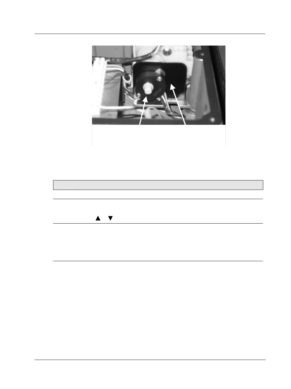
Potentiometer position sensor
Mounting bracket
Figure 29 Location of potentiometer position sensor
Table 31 Load Position Sensor Factory Calibration
Step
Action
1
Reapply AC power to the actuator.
2
Press SET UP key to access the MAINT set up group. Press the FUNCTION key until the
display reads LD CAL.
Press the
or
keys until the display reads POS.
3
Perform the Calibrate Motor procedure exactly as in Table 26 Motor calibration must be
performed for the factory configured full span range (0-100%).
ATTENTION
When calibrating the motor to a short stroke range, you must reset the end-of-travel limit
switches. See Setting End-of-Travel Limit Switches.
4
When motor calibration is complete, the calibration is now stored as the factory calibration of
the actuator motor.