Vent information and diagrams, B. vent system confi guration, A. vent guidelines – Heat & Glo Fireplace SL-550TV-IPI-E User Manual
Page 23
Heat & Glo • SL-550 / 750 / 950TV-IPI-E • 2119-900 Rev. J • 12/09
23
7
7
Vent Information and Diagrams
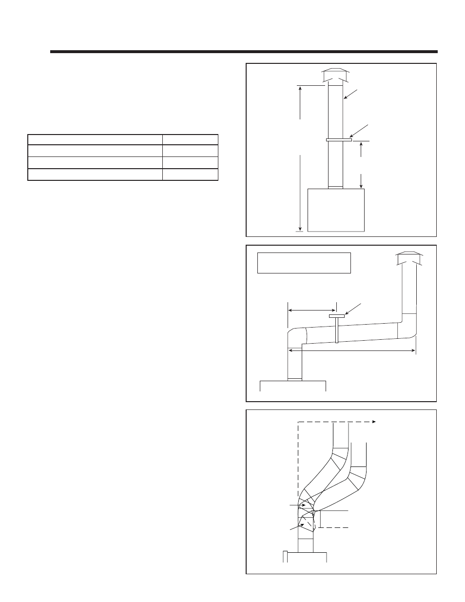
B. Vent System Confi guration
CAUTION! Risk of Fire! ALL vent confi guration speci-
fi cations MUST be followed. This product is tested and
listed to these specifi cations. Appliance performance will
suffer if specifi cations are not followed.
Rise to Run Ratio = 2:1
Maximum Total Horizontal Run = 15 Feet
Minimum Total Vertical Rise = 9 Feet
Maximum Total Vertical Rise = 48 Feet
Maximum Number of Elbows: Two 90º or Four 45º
Figure 7.1
A. Vent Guidelines
WARNING!
Risk of Fire and Asphyxiation! This appliance
requires the specifi ed pipe for operation. Incorrect pipe may
cause spillage, condensation and overheating.
Figure 7.2
These models require the following size B-vent double
wall, or single wall rigid or fl ex vent pipe.
METAL
PLUMBERS' STRAP
MAXIMUM HORIZONTAL RUN IS 50%
OF VERTICAL. HORIZONTAL RUN
CANNOT BE MORE THAN 15 FT.
VENT SUPPORTS
ARE PER VENT
MANUFACTURER'S
SPECIFICATIONS.
METAL
PLUMBER’S
STRAP
9 FEET
MINIMUM
48 FEET
MAXIMUM
VENT SUPPORTS ARE PER
VENT MANUFACTURER’S
SPECIFICATIONS
MINIMUM CLEARANCES
ARE PER VENT
MANUFACTURER’S
SPECIFICATIONS
• Follow pipe manufacturer’s installation guidelines when
installing the appliance.
Models
Pipe Size
SL-550TV-IPI-E
5 inch
SL-750TV-IPI-E
5 inch
SL-950TV-IPI-E
6 inch
WARNING! Risk of Fire, Explosion or Asphyxiation!
DO NOT connect this gas appliance to a chimney fl ue
serving a separate solid-fuel or gas burning appliance.
• Vent this appliance directly outside.
• Use separate vent system for this appliance.
May impair safe operation of this appliance or other appli-
ances connected to the fl ue.
WARNING! Risk of Fire or Explosion! Insulation and
other combustibles must not infringe on clearances.
• ALWAYS maintain specifi ed clearances around venting
and fi restop systems.
• Install fi restops as specifi ed.
Failure to keep insulation or other material away from vent
pipe may cause fi re.
Figure 7.3
45 DEGREES
ELBOW
90 DEGREES
ELBOW
OFFSETS EXCEEDING
45 DEGREES ADAPT
HORIZONTAL LIMITATIONS
MAXIMUM
HORIZONTAL
15 FEET
MINIMUM
VERTICAL
9 FEET
Note: Maximum horizontal
distance is 50% vertical vent
height.
Note: Horizontal runs require
1/4 in. rise per foot run.