Cl36d and cr36d installation instructions, Using offsets and returns, Table 1 offset chart – Hearth and Home Technologies CL36D User Manual
Page 13
02-02
13
12538 Rev D
CL36D AND CR36D INSTALLATION INSTRUCTIONS
WARNING!
Do not combine offsets to create an offset greater than 30° from vertical.
This may create a fire hazard since the natural draft may be restricted.
1. Using Offsets and Returns
a. To bypass any overhead obstructions, the chimney may be offset using a 15° (SL315) or a 30° (SL330) offset/
return. Perform the following steps to determine the correct chimney component combination for your particular
installation.
b. An offset and return may be attached together or a chimney section(s) may be used between an offset and
return.
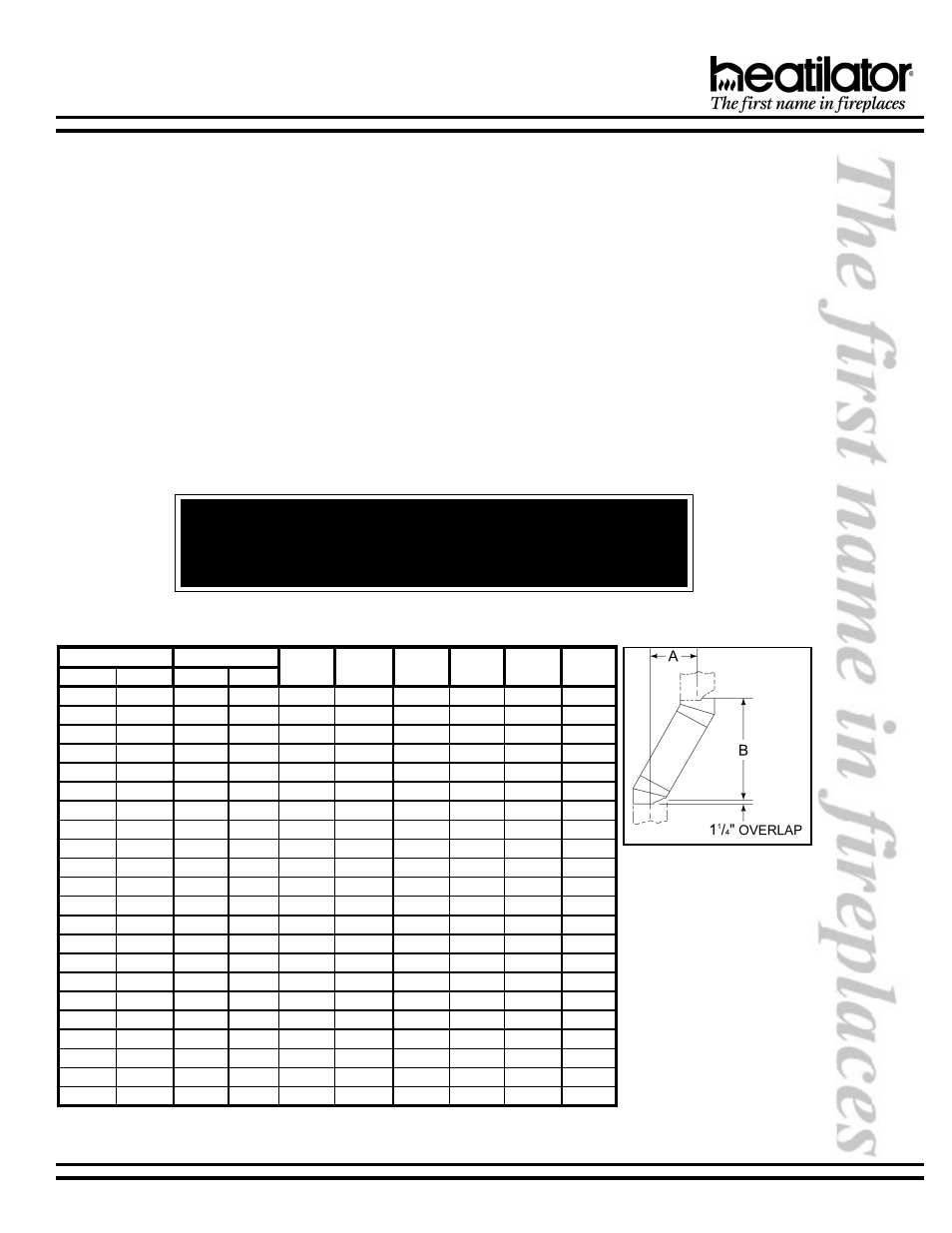
1) Measure how far the chimney needs to be shifted to enable it to avoid the overhead obstacle. See Figure 5,
dimension A to determine chimney sections required to achieve the needed shift.
2) After determining the offset dimension, refer to Table 1 and find the A dimension closest to but not less
than the distance of shift needed for your installation.
3) The B dimension that coincides with the A dimension represents the required vertical clearance that is
needed to complete the offset and return.
4) Read across the chart and find the number of chimney sections required and the model number of those
particular chimney parts.
5) Whenever the chimney penetrates a floor/ceiling, a firestop spacer must be installed.
6) The effective height of the fireplace assembly is 38½ and is measured from the base of fireplace to top
of starter collar.
Example:
Your
A
dimension from Figure 7 is
14½. Using Table 1 the
dimension closest to, but
not less than 14½ is 14
5
/
8
using a 30° offset/return. It
is then determined from the
table that you would need
33
(Dimension
B)
between the offset and
return. The chimney
components that best fit
your application are two
SL312s.
Figure 5 - Chimney Offset/
Return
* Proper assembly of air cooled chimney parts result in an overlap at chimney
joints of 1¼. Effective length is built into this chart.
°
5
1
°
0
3
6
0
3
L
S
2
1
3
L
S
8
1
3
L
S
4
2
3
L
S
6
3
3
L
S
8
4
3
L
S
A
B
A
B
1
5
/
8
"
3
1
3
/
8
"
3
7
/
8
"
4
1
1
/
2
"
-
-
-
-
-
-
2
7
/
8
"
7
1
3
/
4
"
6
1
/
4
"
8
1
5
/
8
"
1
-
-
-
-
-
-
-
8
5
/
8
"
"
¾
2
2
2
-
-
-
-
-
4
1
/
2
"
3
2
5
/
8
"
9
1
/
4
"
3
2
3
/
4
"
-
1
-
-
-
-
-
-
1
1
5
/
8
"
7
2
7
/
8
"
1
1
-
-
-
-
"
6
9
2
3
/
8
"
2
1
1
/
4
"
"
9
2
-
-
1
-
-
-
7
1
/
4
"
"
4
3
4
1
5
/
8
"
"
3
3
-
2
-
-
-
-
-
-
5
1
1
/
4
"
4
3
1
/
8
"
-
-
-
1
-
-
-
-
7
1
5
/
8
"
8
3
1
/
4
"
1
-
-
1
-
-
-
-
0
2
5
/
8
"
3
4
1
/
2
"
-
-
2
-
-
-
0
1
5
/
8
"
6
4
3
/
4
"
1
2
1
/
4
"
4
4
5
/
8
"
-
-
-
-
1
-
1
1
7
/
8
"
1
5
3
/
8
"
3
2
5
/
8
"
8
4
3
/
8
"
1
-
-
-
1
-
-
-
6
2
5
/
8
"
3
5
7
/
8
"
-
-
-
2
-
-
3
1
3
/
4
"
8
5
3
/
8
"
7
2
1
/
4
"
5
5
3
/
4
"
-
-
-
-
-
1
"
5
1
"
3
6
9
2
5
/
8
"
"
9
5
1
-
-
-
-
1
6
1
1
/
2
"
8
6
3
/
4
"
2
3
5
/
8
"
4
6
1
/
4
"
-
1
-
-
-
1
"
8
1
4
7
5
/
8
"
5
3
5
/
8
"
9
6
1
/
2
"
-
-
1
-
-
1
-
-
8
3
5
/
8
"
4
7
5
/
8
"
-
-
-
1
-
1
-
-
"
1
4
8
7
3
/
4
"
1
-
-
1
-
1
2
2
3
/
4
"
1
9
7
/
8
"
4
4
5
/
8
"
"
5
8
-
-
-
-
1
1
"
4
2
6
9
1
/
2
"
"
7
4
9
8
1
/
8
"
1
-
-
-
1
1
5
2
7
/
8
"
3
0
1
1
/
2
"
0
5
5
/
8
"
5
9
1
/
2
"
-
-
-
-
-
2
Table 1
Offset Chart*