Electrical information, Warning, Caution – Heat & Glo Fireplace 6000G-IPI User Manual
Page 38
Heat & Glo • 6000G, 6000G-IPI • 2103-900 Rev. M • 9/08
38
Optional Accessories Requirements
Wiring for optional accessories should be done now to
avoid reconstruction.
• This appliance may be used with a wall switch, wall
mounted thermostat and/or a remote control.
• If using thermostat use one compatible with a millivolt
gas valve system.
• Follow parameters for locating thermostat (see individual
thermostat instructions) to ensure proper operation of
appliance.
• Use low resistance thermostat wire for wiring from igni-
tion system to the wall switch and thermostat.
• Keep wire lengths short as possible by removing any
excess wire length.
• Low voltage and 110 VAC voltage cannot be shared
within the same wall box.
A. Recommendation for Wire
This appliance requires 110-120 VAC be wired to the
junction box either for use of optional accessories (stand-
ing pilot ignition) or for proper operation of the appliance
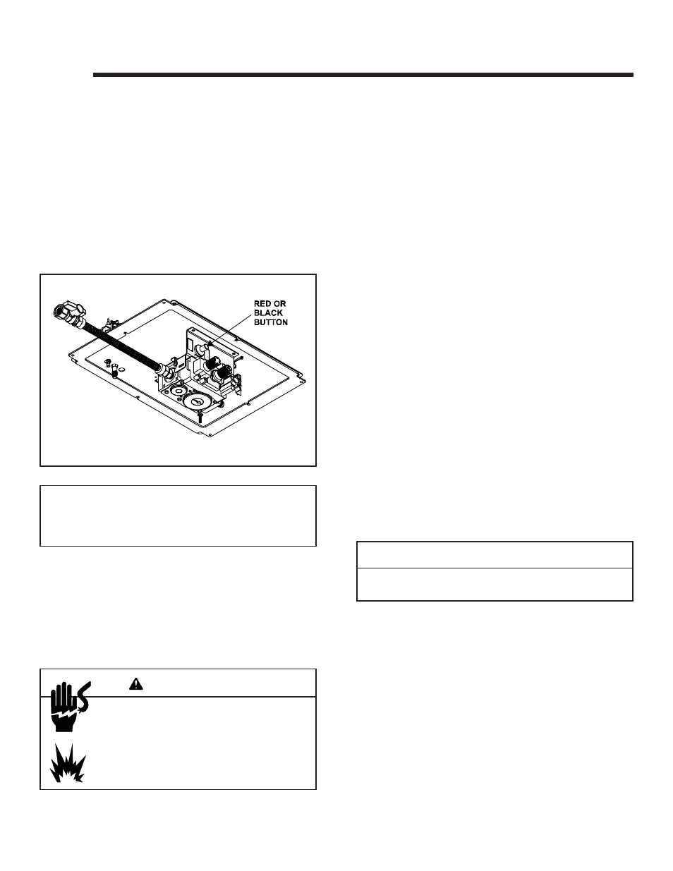
(Intellifi re ignition). Refer to Figure 10.1 to determine if the
appliance uses an Intellifi re ignition system or Standing
Pilot ignition system.
Open the control access panel to view wiring system and
gas valve. If this appliance has a red or black ignitor button
(as noted in Figure 10.1) this appliance has a Standing Pilot
ignition system. If there is no red or black ignitor button,
this appliance has an Intellifi re ignition system.
Figure 10.1 Standing Pilot Ignition
10
10
Electrical Information
Note: This appliance must be electrically wired and grounded
in accordance with local codes or, in the absence of local
codes, with National Electric Code ANSI/NFPA 70-latest
edition or the Canadian Electric Code, CSA C221.1.
B. Connecting to the Appliance
Wire 110V to electrical junction box.
Do NOT wire 110V to valve.
Do NOT wire 110V to wall switch.
• Incorrect wiring will damage millivolt valves.
• Incorrect wiring will override IPI safety lockout
and may cause explosion.
WARNING
C. Intellifi re Ignition System Wiring
This appliance requires a 110 VAC supply to the appliance
junction box for operation. A wiring diagram is shown in
Figure 10.2.
This appliance is equipped with an Intellifi re control valve
which operates on a 3 volt system.
This appliance is supplied with a battery pack and a 3 volt
AC transformer, which requires the installation of the sup-
plied junction box. It is highly recommended that the junc-
tion box be installed at this time to avoid reconstruction.
The battery pack requires two D cell batteries (not includ-
ed). Batteries cannot be placed in the battery pack while
using the 3 volt transformer. Batteries shouldn’t be placed
into the holder until needed. The higher temperatures will
shorten their life.
CAUTION
Battery polarity must be correct or module damage will
occur.
• A 110-120 VAC circuit for this product must be protected
with ground-fault circuit-interrupter protection, in
compliance with the applicable electrical codes, when
it is installed in locations such as in bathrooms or near
sinks.