Control board layout, G" control board – Hoshizaki KM-1301SAH/3 User Manual
Page 22
22
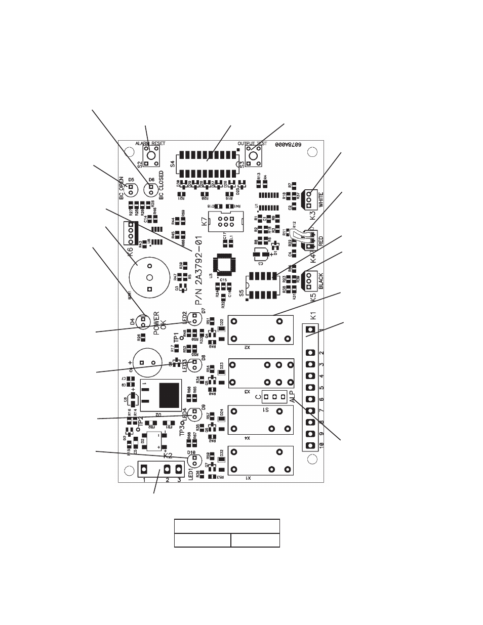
1. Control Board Layout
Control Board
Part Number 2A3792-01
"G" Control Board
"ALARM RESET" Button
"OUTPUT TEST" Button
(used to test relays on control board)
WHITE K3 Connector
Harvest Control
(thermistor)
RED K4 Connector
K4 Jumper (4A4883G01
thermostatic bin control
application) or Mechanical
Bin Control
Label
(control board revision
level indicated on label
on side of relay)
BLACK K5 Connector
Float Switch
Part Number
K1 Ten-Pin Connector
Pins #1 through #10
#1, 9 Magnetic Contactor
#2 Hot Gas Valve (HGV)
#3 Liquid Line Valve (LLV),
Fan Motor (FM)
#4 Pump Motor (icemaking)
#5 Pump Motor (pump-out,
harvest (if applicable))
#6 Inlet Water Valve (WV)
#7, 10 Component Power
Supply
#8 Open
Switch for "C" control board
and "ALPINE" control board
(service control board only)
Bin Control Switch
Open LED (yellow)
(mechanical bin control
application only)
S4 Dip
Switch
Bin Control Switch
Closed LED (green)
(on continuously
in thermostatic bin
control application)
Alarm Buzzer
Power LED (red)
(lights when
power is supplied to
the control board)
LED 2 (X2 Relay)
Hot Gas Valve (HGV)
Fan Motor (FM)
(FM off when LED on)
LED 3 (X3 Relay)
Pump Motor (PM)
(on at pump-out,
harvest (if applicable))
LED 4 (X4 Relay)
Inlet Water Valve (WV)
LED 1 (X1 Relay)
Compressor (Comp),
Fan Motor-Remote
(FMR)
K2 Connector
Transformer
S5 Dip Switch
Relay LEDs (4)
(indicate which
relays are energized
as listed below)