Hoshizaki JWE-620UA-6B User Manual
Page 66
61
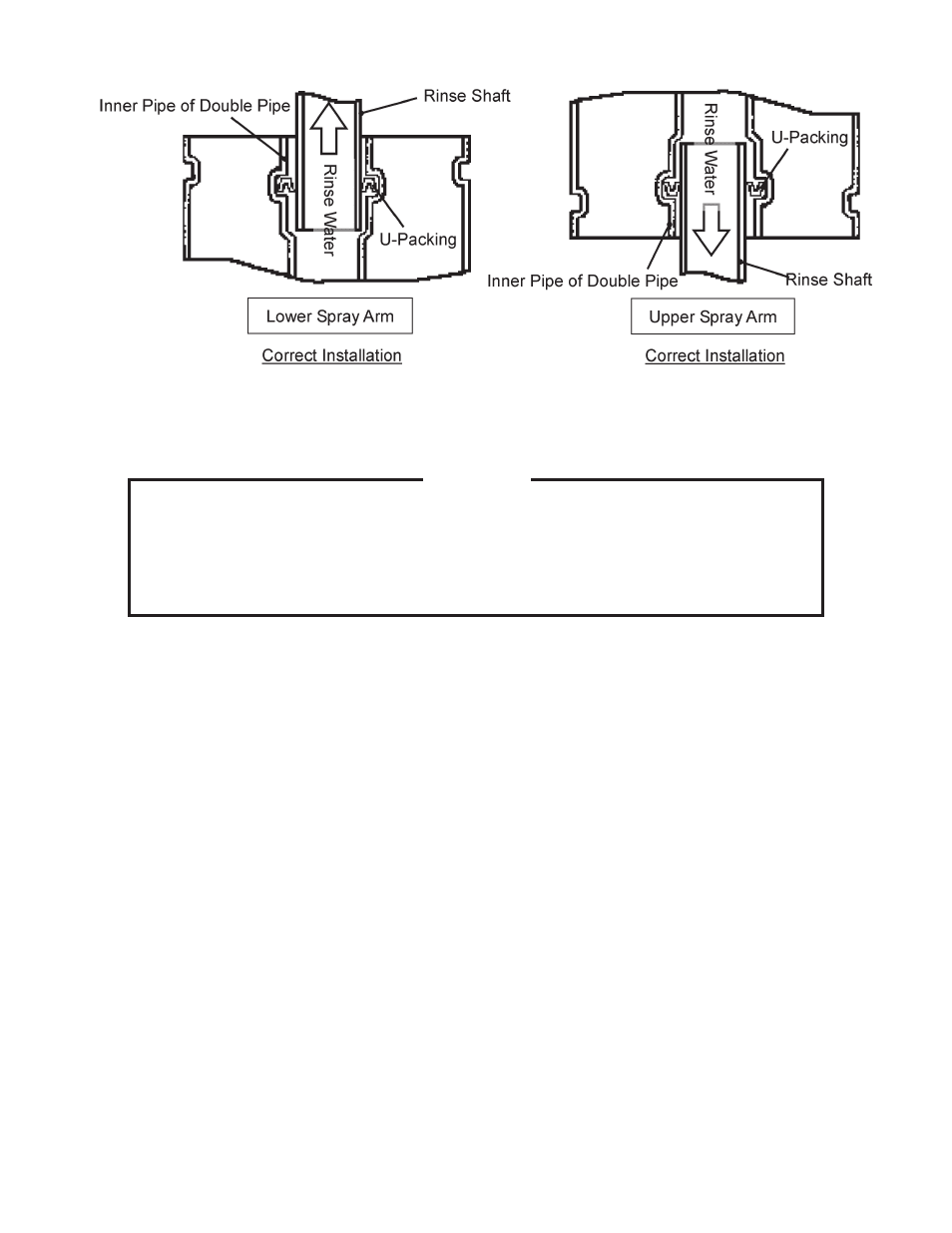
3) Header (Rinse Spray Arm) and Double Pipe Connection
M. Removal and Replacement of Thermistor
NOTICE
1. The thermistors are fragile; handle very carefully.
2. Always use the recommended sealant (high thermal conductive type), Model
KE4560RTV manufactured by SHINETSU SILICONE, Part Code 60Y000-11,
or Part Code 4A0683-01 or equivalent.
3. Do not shorten or cut the thermistor leads.
1)
Move the power switch (GFCI) to the “OFF” position, then turn off the power supply.
Lockout/Tagout to prevent the power from being turned back on inadvertently.
2) Remove the front panel.
3) Remove the plastic bag covering the thermistor connector, then disconnect the thermistor
connector. If replacing the wash tank thermistor, disconnect the leads from the wash tank
electrode. If replacing the internal booster tank thermistor, disconnect the closed end
connectors for the internal booster tank water level fl oat switch and the internal booster
tank backup water level fl oat switch.
4) Remove the tape or ties securing the thermistor leads, then pull out the thermistor from
the wash tank or internal booster tank straight towards you.
5) Clean out all old sealant from inside the thermistor hole.
6) Route the wires from the new thermistor connector through the existing black plastic
sleeve.
7) Apply the recommended sealant (
KE4560RTV, Part Code 60Y000-11 or 4A0683-01)
to the end of the new thermistor, then insert the thermistor quickly and securely.
8) Use tape or ties to secure the thermistor leads in their correct position.
9) Reconnect the thermistor connector and the wash tank electrode leads or the internal
booster tank water level fl oat switch and internal booster tank backup water level fl oat
switch leads, then bag and tie them.
10) Replace the front panel in its correct position.