Hoshizaki JWE-620UA-6B User Manual
Page 20
15
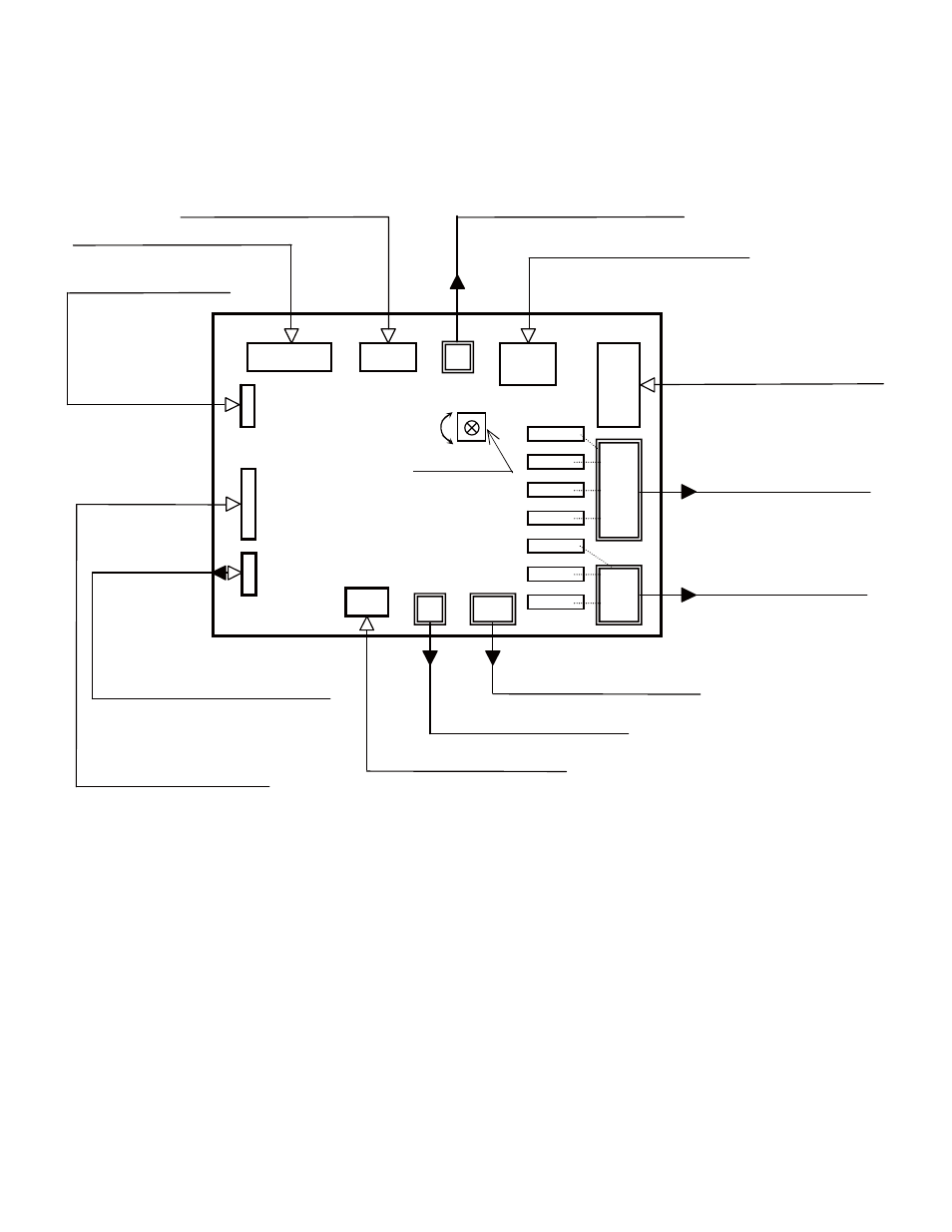
2. Control Board Layout
Inputs and outputs are laid out on the control board as illustrated below.
Buzzer Output XA Connector (2P)
Signal Input XA Connector (6P)
Power Input VH Connector (6P)
Output VH Connector (7P)
Output VH Connector (5P)
X1
X2
X3
X4
X5
X6
X7
CN8
CN9
CN10
CN1
CN7
CN6
CN5
CN11
CN13
CN12
CN4
CN2
CN3
1 4
1
6
1
10
1
1
6
2
1
1
7
5
1
3
1
1
2
3
1
5
1
8
1
4
VR1
Signal Input XA Connector (10P)
Power Input VH Connector (4P)
XH Connector (3P): not in use
XH Connector (2P): not in use
XA Connector (3P): not in use
Operation Board XA Connector (5P)
Heater Control Signal Input
XA Connector (8P)
Thermistor Signal Input
XA Connector (4P)
Buzzer Volume
High
Low