Chapter 4 explanation of functions – Hitachi SJ700-2 User Manual
Page 129
Chapter 4 Explanation of Functions
Intelligent output terminals
When "4 bits" is selected
When "3 bits" is selected
14 13 12 11
AC3 AC2 AC1 AC0
Factor code
Cause of tripping
Factor code
Cause of tripping
1 1 0 1 E20,
E21
Temperature error due to
low cooling-fan speed
Temperature error
-
-
1
1
1
0
E24
Phase loss input protection
-
-
1 1 1 1 E50
to
E79
Easy sequence user trip 0-9,
option 1,2 error 0-9
-
-
Item Function
code
Data
Description
00
No output of alarm code
01
Output of 3-bit code
Alarm code output
C062
02
Output of 4-bit code
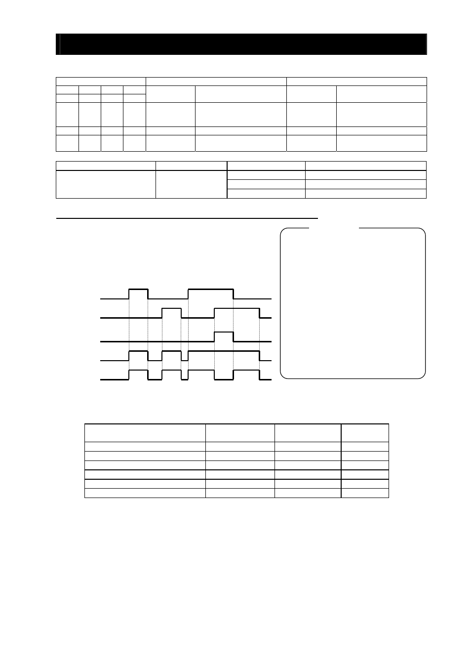
4.2.66 Logical output signal operation function (LOG1 to LOG6)
C021 to C025: Terminal [11] to [15] functions
C026: Alarm relay terminal function
C142: Logical output signal 1 selection 1
C143: Logical output signal 1 selection 2
C144: Logical output signal 1 operator selection
C145: Logical output signal 2 selection 1
C146: Logical output signal 2 selection 2
C147: Logical output signal 2 operator selection
C148: Logical output signal 3 selection 1
C149: Logical output signal 3 selection 2
C150: Logical output signal 3 operator selection
C151: Logical output signal 4 selection 1
C152: Logical output signal 4 selection 2
C153: Logical output signal 4 operator selection
C154: Logical output signal 5 selection 1
C155: Logical output signal 5 selection 2
C156: Logical output signal 5 operator selection
C157: Logical output signal 6 selection 1
C158: Logical output signal 6 selection 2
C159: Logical output signal 6 operator selection
Related code
The logical output signal operation function allows you to make
the inverter internally perform a logical operation of output
signals.
This function applies to all output signals, except to logical
operation results (LOG1 to LOG6).
Three types of operators (AND, OR, and XOR) are selectable.
LOGx (AND)
LOGx (OR)
LOGx (XOR)
Output signal 1
Output signal 2
The necessary parameters depend on the logical output signal to be operated. The following table lists the
parameters to be set for each logical output signal:
Selected signal
Operation-target 1
selection
Operation-target 2
selection
Operator
selection
33: Logical output signal 1 (LOG1)
C142
C143
C144
34: Logical output signal 2 (LOG2)
C145
C146
C147
35: Logical output signal 3 (LOG3)
C148
C149
C150
36: Logical output signal 4 (LOG4)
C151
C152
C153
37: Logical output signal 5 (LOG5)
C154
C155
C156
38: Logical output signal 6 (LOG6)
C157
C158
C159
(Example) To output the AND of the running signal (00: RUN) and set the frequency overreached signal
(02: FA2) as the logical output signal 1 (LOG1) to the intelligent output terminal [2]:
- Intelligent output terminal [2] (C002): 33 (LOG1)
- Logical output signal 1 selection 1 (C142): 00 (RUN)
- Logical output signal 1 selection 2 (C143): 02 (FA2)
- Logical output signal 1 operator (C143): 00 (AND)
4 -
66