Functions, Compressor area set up, Assembly – Harbor Freight Tools CENTRAL PNEAMATIC 95386 User Manual
Page 9
Page 9
For technical questions, please call 1-800-444-3353.
SKU 95386
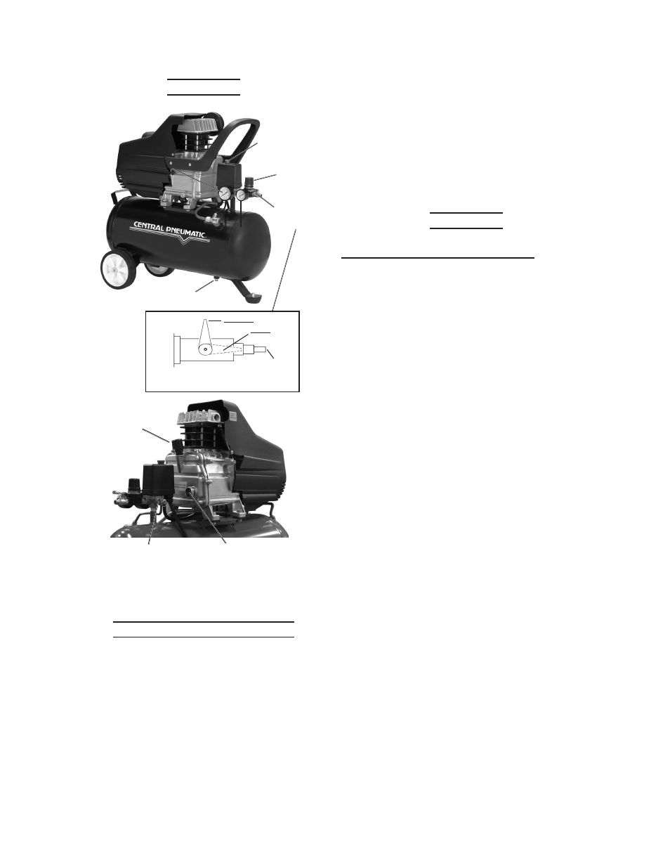
Functions
connect
aIr HoSe
Here.
cloSed
oPen
Regulator
(58)
Air Outlet
Valve (59)
Figure 1
ON/OFF Power
Button
(On Pressure
Switch (55))
Oil Sight Glass
(33)
Oil Plug (31)
Safety Valve
(56)
Tank Pressure
Gauge (54)
Output
Pressure
Gauge
(60)
Drain Valve (65)
air outlet Valve (59)
(toP VIeW)
compressor area Set up
Designate a work area that is clean
1.
and well-lit. The work area must not
allow access by children or pets to
prevent injury.
Locate the Compressor on a flat
2.
level surface to ensure proper pump
lubrication and to prevent damage to
the unit. Keep at least 12” of space
around the unit to allow air circulation.
Route the power cord from the
3.
compressor to the grounded wall
outlet, along a safe path without
creating a tripping hazard or exposing
the power cord to possible damage.
assembly
attaching the Foot and Wheels
To attach the Foot (66) to the front
1.
bottom of the Air Tank (1):
Using the Bolt/Washer/Nut Assembly
a.
(67), slide a flat washer onto the
Bolt.
Slide the Bolt through the Foot and
b.
the hole in the Air Tank front leg.
Slide a flat washer and the lock
c.
washer onto the bolt and secure in
place with the nut.
To attach the Wheels (5) to the back
2.
bottom of the Air Tank (1):
Slide the Wheel Shaft Bolt (6)
a.
through the Wheel (5), a Flat
Washer (4), and the hole in the leg
of the Air Tank.
Slide the remaining Flat Washer (4)
b.
and Lock Washer (3) onto the Wheel
Shaft Bolt and secure in place with
the Nut (2).
Repeat step (a) and (b) for the other
c.
Wheel.