Henny Penny ISLAND WARMER HMI-105 User Manual
Page 9
Model
HMI-103/105
SECTION 2. MAINTENANCE
2-1. INTRODUCTION
This section provides procedures for check out and replacement
of the various parts used within the cabinet. Before replacing
any parts, refer to the Troubleshooting Section. It will aid you
in determining the cause of the malfunction.
2-2. TEST INSTRUMENTS
You may want to use two test instruments to check the electric
components.
1. A continuity light
2.
An
ohmmeter
When the manual refers to a circuit being closed, the continuity
light will be illuminated or the ohmmeter should read zero
unless otherwise noted.
When the manual refers to a circuit being open, the continuity
light will not illuminate or the ohmmeter will read 1 (one) or
infi nite resistance.
A continuity tester cannot be used to check coils.
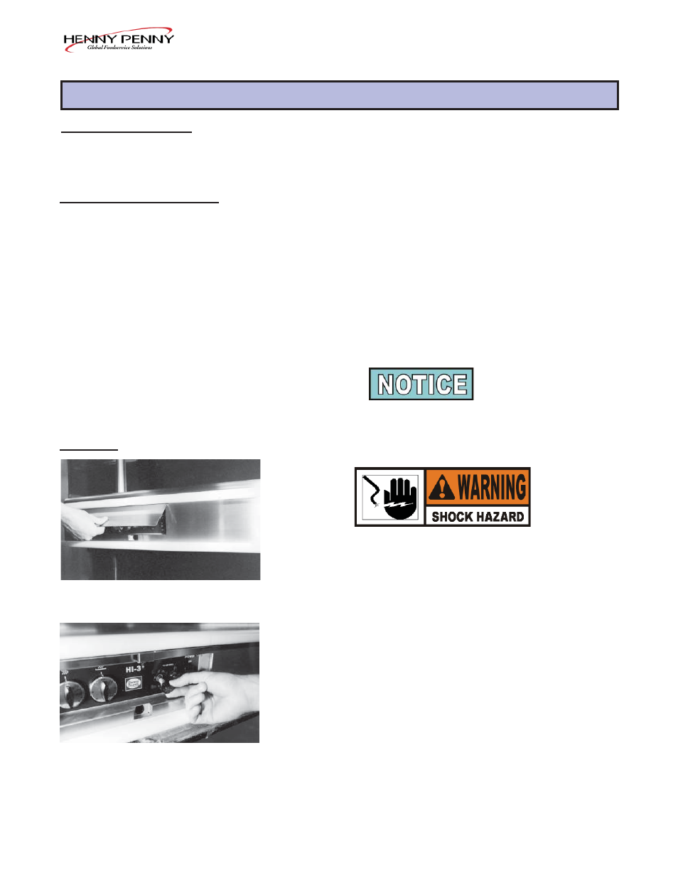
2-3. FUSE
1. Remove electrical power supplied to the unit.
To avoid electrical shock or property damage, move
power switch to OFF and disconnect main circuit
breaker, or unplug cord at wall receptacle.
2. Open the control panel cover and locate both fuse holders.
3. Unscrew the caps, counterclockwise, and pull fuses from
holders.
4. Place leads of meter on each end of a fuse, and check for
continuity on both fuses. If one shows an open circuit,
replace it with a 15 amp fuse (HP no. EF02-007).
203
2-1
Step 2
Step 3