F. junction box installation – Hearth and Home Technologies BCBV36I User Manual
Page 28
Heatilator • BCBV36 • 4008-033 • Rev F • 12/08
28
F. Junction Box Installation
Your appliance is supplied with a Junction Box Kit. To
operate the appliance with the supplied 3VAC transformer
and/or remote control option, it is recommended that the
junction box be installed and wired at this time to avoid
reconstruction.
• The Junction Box Kit is to be installed on the right
side of the appliance; remove and discard the metal
knockout.
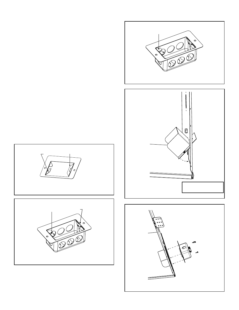
• Attach the junction box bracket to the junction box as
shown in Figures 12.4-12.6.
• Bring the electrical wires to the inside of the junction box
and secure in place with the Romex connector.
• Install the duplex receptacle in the junction box and
attach the cover plate.
• Prior to attaching the junction box to the appliance,
the heat shield supplied with your appliance must
be installed. Insert the top fl ange of the heat shield
through the electrical knockout hole from the inside
(Figure 12.7).
• Attach the junction box bracket to the side of the
appliance. See Figure 12.8. Secure with the screws
provided in the fastener package.
• Install the fan kit (if desired). See instructions supplied
with the kit for details.
• Wire the junction box per the diagram in Figure 12.2.
Figure 12.7 Attach the Heat Shield
Note: Do NOT wire 110
VAC to wall switch.
Figure 12.8 Attach the Junction Box
Bend this tab down
90 degrees
Bend this half tab
down 90 degrees
Figure 12.4 Prepare Junction Box Bracket
Slide the flanges of the junction box
through the slots in the bracket.
Figure 12.5 Position Bracket on Junction Box
Bend remaining half
tab down 90 desgrees.
Figure 12.6 Secure Bracket to Junction Box