E. electrical service and repair – Hearth and Home Technologies BCBV36I User Manual
Page 27
Heatilator • BCBV36 • 4008-033 • Rev F • 12/08
27
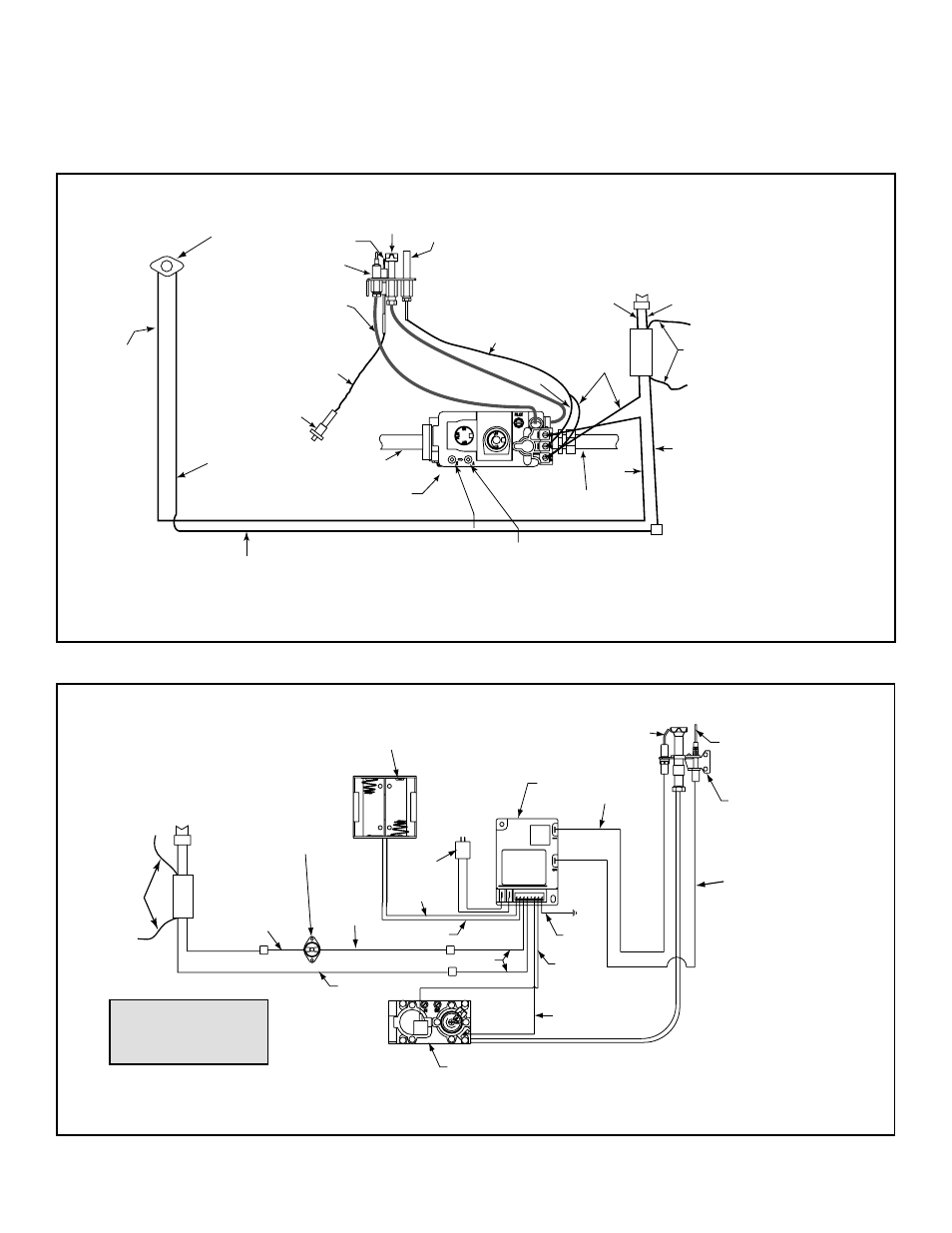
Ignitor
Flame
Sensor
Pilot Assembly
GRN
ORG
BLK
ORG
Control
Box
To
Junction
Box
Battery
Pack
3V
Adaptor
BLK
BRN
RED
RED
BLK
BLU
Valve
Limit
Switch
WHT
+
- +
-
Optional SPST
Wall Switch
OR
Optional Remote
WHT
GRN*
* GRN wire only used with
optional wall switch
WSK-MLT-HTL
E. Electrical Service and Repair
WARNING! Risk of Shock! Label all wires prior to
disconnection when servicing controls. Wiring errors can
cause improper and dangerous operation. Verify proper
operation after servicing.
Figure 12.3 Intellifi re Pilot Ignition (IPI) Wiring Diagram
Figure 12.2 Standing Pilot Ignition Wiring Diagram
WARNING! Risk of Shock! Replace damaged wire with
type 105° C rated wire. Wire must have high temperature
insulation.
Pilot
Ignitor
GAS
VALVE
To Burner
Gas Inlet
Inlet Tap
ORG
TAN
Thermopile
WHT
RED
Flame Sensor
Copper
Tubing
Push
Button
Ignitor
Outlet Tap
Wall Switch (or
thermostat if
heater-listed)
WHT
RED
GRN wire only used with
optional wall switch
WSK-MLT-HTL
HIGH
LIMIT
SWITCH
BLK
BLK
BLU
BLU
Pilot T
ube
WHT
- WHB33 (4 pages)
- WTBC36DB (4 pages)
- Direct Vent Gas Appliance CD4236R (80 pages)
- Heat & Glo Twilight II-B (40 pages)
- CFX-Crescent (38 pages)
- GO40SP-REM-LP (27 pages)
- 6000G (74 pages)
- A36C (48 pages)
- I80 (56 pages)
- Heatilator FL92 (48 pages)
- Direct Vent Gas Appliance CNXT4842ILH (80 pages)
- Birmingham (4 pages)
- A36RH (48 pages)
- TIARAI-CTO (60 pages)
- Accelerator C 42 48 30-7 (2 pages)
- IDV6247IH (64 pages)
- 8000CFLP-OAKIPI (62 pages)
- Fireside Furnishings Fireplace Cast Mantels (8 pages)
- EPA Certified Woodburning Fireplace 7100FP-BK-B (72 pages)
- Heatilator GDST5244I (60 pages)
- BIR42 (56 pages)
- 823-0290 (32 pages)
- HUDBAY-INS (37 pages)
- Yosemite MBK (32 pages)
- Heat & Glo SL-750TR-D (74 pages)
- GAS STOVE PIER-TRC (40 pages)
- Direct Vent Gas Appliance EDV3633 (60 pages)
- Direct Vent Room Heater SAPPH-D-CWL (56 pages)
- GDST3831I (62 pages)
- BE-36-C (37 pages)
- Grand-XTS (45 pages)
- BAY-40 (52 pages)
- Balanced Flue Gas Fireplace SOHO-CE (4 pages)
- GDCR4136I (88 pages)
- 299-900D (4 pages)
- Cosmo SLR (2 pages)
- DV3732SBI (77 pages)
- Balanced Flue Gas Fireplace CORNER-HVB-CE (2 pages)
- Hudson Bay Direct Vent Gas Appliance HUDBAY-FS (49 pages)
- Direct Vent Gas Appliance CD4842MILR (76 pages)
- I100 (52 pages)
- CNXT4842 (4 pages)
- EL42 (54 pages)
- GBI25 (24 pages)
- Heat-N-Glo Dakota 42H (36 pages)