Hearth and Home Technologies BCBV36I User Manual
Page 13
Heatilator • BCBV36 • 4008-033 • Rev F • 12/08
13
Burner Ignition and Operation
Frequency: Annually
By: Qualifi ed Service Technician
Tools needed:
Protective gloves, vacuum cleaner, whisk
broom, fl ashlight, voltmeter, indexed drill bit set, and a manom-
eter.
• Verify burner is properly secured and aligned with pilot
or igniter.
• Clean off burner top, inspect for plugged ports, corrosion
or deterioration. Replace burner if necessary.
• Replace ember materials with new dime-size pieces.
DO NOT block ports or obstruct lighting paths. Refer to
Section 14 for proper ember placement.
• Verify batteries have been removed from battery back-
up IPI systems to prevent premature battery failure or
leaking.
• Check for smooth lighting and ignition carryover to all
ports. Verify that there is no ignition delay.
• Inspect for lifting or other fl ame problems.
Control Compartment and Firebox Top
Frequency: Annually
By: Qualifi ed Service Technician
Tools needed:
Protective gloves, vacuum cleaner, dust cloths
• Vacuum and wipe out dust, cobwebs, debris or pet hair.
Use caution when cleaning these areas. Screw tips that
have penetrated the sheet metal are sharp and should
be avoided.
• Remove all foreign objects.
• Verify unobstructed air circulation.
Firebox
Frequency: Annually
By: Qualifi ed Service Technician
Tools needed:
Protective gloves, sandpaper, steel wool,
cloths, mineral spirits, primer and touch-up paint.
• Inspect for paint condition, warped surfaces, corrosion
or perforation. Sand and repaint as necessary.
• Replace
fi replace if fi rebox has been perforated.
Logs
Frequency: Annually
By: Qualifi ed Service Technician
Tools needed:
Protective gloves.
• Inspect for damaged or missing logs. Replace as
necessary. Refer to Section 14.I. for log placement
instructions.
• Verify correct log placement and no fl ame impingement
causing sooting. Correct as necessary.
• Verify air shutter setting is correct. See Section 14.K.
for required air shutter setting. Verify air shutter is clear
of dust and debris.
• Inspect
orifi ce for soot, dirt and corrosion. Verify orifi ce
size is correct. See Service Parts List for proper orifi ce
sizing.
• Verify manifold and inlet pressures. Adjust regulator as
required.
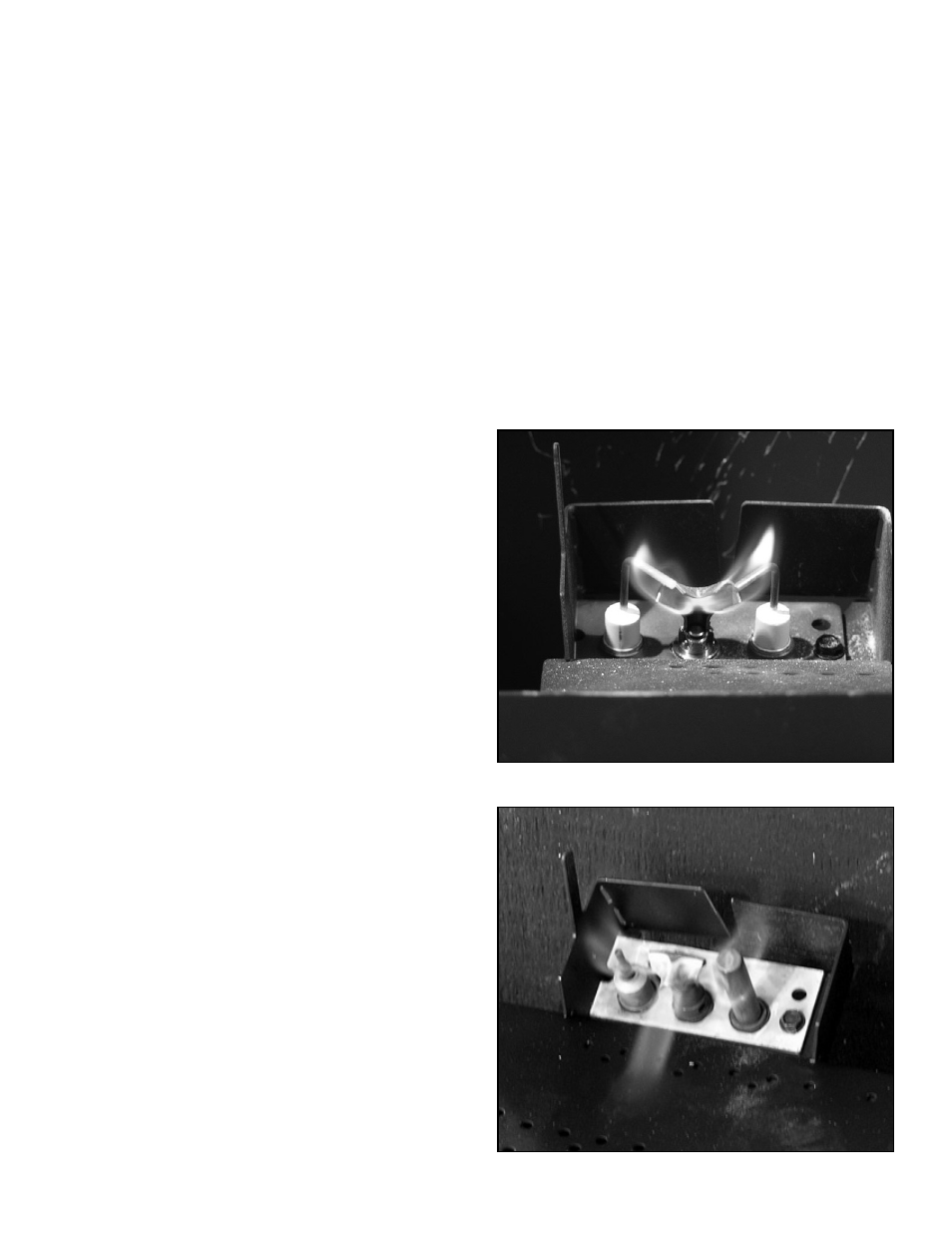
• Inspect
pilot
fl ame pattern and strength. See Figure 3.1
and 3.2 for proper pilot fl ame pattern. Clean or replace
orifi ce spud as necessary.
• Inspect thermocouple/thermopile or IPI fl ame sensing
rod for soot, corrosion and deterioration. Clean with
emery cloth or replace as required.
• Verify thermocouple/thermopile millivolt output. Replace
pilot as necessary. (Standing pilot only)
• Verify that there is not a short in fl ame sense circuit by
checking continuity between pilot hood and fl ame sense
rod. Replace pilot as necessary. (IPI only)
Figure 3.1 IPI Pilot Flame Patterns
Figure 3.2 Standing Pilot Flame Patterns