C. service parts (continued), Ipi v alve assembly – Hearth and Home Technologies IDV4833ILH User Manual
Page 62
Heatilator • ICON DV-IDV Series • 4042-575 • Rev K • 11/08
62
C. Service Parts (continued)
Service Parts
10/08
IMPOR
TANT
: THIS IS DA
TED INFORMA
TION. When requesting service or replacement
parts for your appliance please provide model number and serial number
. All parts listed
in this manual may be ordered from an authorized dealer
.
Stocked
at Depot
ITEM
D
ESCRIPTION
COMMENTS
P
A
RT NUMBER
IDV6247 T
raditional Refractory
P
re GA1732717
Post GA1732717
1
Left Side Refractory Panel
4042-414
4042-738
2
Refractory Retainer Bracket
(qty 3 req.)
4042-291
3
Left Hearth Refractory
4042-420
4042-744
4
Hearth Refractory
4042-413
4042-737
5
B
ack Refractory Panel
4042-409
4042-733
6
Right Hearth Refractory Panel
4042-421
4042-745
7
Right Side Refractory Panel
4042-415
4042-739
8
F
ront Refractory Kit
4042-456
4042-756
9
Left Front Refractory
4042-456
4042-761
10
Right Front Refractory
4042-456
4042-760
11
Front Hearth Refractory
4042-467
4042-767
IDV6247 Herringbone Refractory
P
re
April 2004
Post
April 2004
1
Left Side Refractory Panel
4042-416
4042-740
2
Refractory Retainer Bracket
(qty 3 req.)
4042-291
3
Left Hearth Refractory
4042-420
4042-744
4
Hearth Refractory
4042-413
4042-737
5
B
ack Refractory Panel
4042-41
1
4042-735
6
Right Hearth Refractory Panel
4042-421
4042-745
7
Right Side Refractory Panel
4042-417
4042-741
8
F
ront Refractory Kit
4042-457
4042-757
9
Left Front Refractory
4042-457
4042-765
10
Right Front Refractory
4042-457
4042-764
11
Front Hearth Refractory
4042-467
4042-767
Additional service part numbers appear on following page.
IDV6247IT
, IDV6247IH
47 in. ICON Gas
Appliance - DV
7
1
5
4
3
6
2
8 - Front
Refractory Kit
11
10
9
Refractory Parts Diagram
Beginning Manufacturing Date: Jan. 2007
Ending Manufacturing Date:
Active
Service Parts
10/08
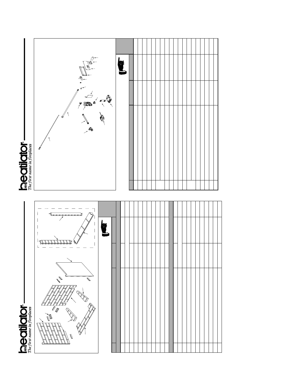
IDV6247IT
, IDV6247IH
47 in. ICON Gas
Appliance - DV
V
alve
Assembly Diagram/ Parts List
8
6
5
2
3
4
7
9
10
11
12
13
14
15
17
16
1
IMPOR
TANT
: THIS IS DA
TED INFORMA
TION. When requesting service or replacement
parts for your appliance please provide model number and serial number
. All parts listed
in this manual may be ordered from an authorized dealer
.
Stocked
at Depot
ITEM
D
ESCRIPTION
COMMENTS
P
A
RT NUMBER
1
P
ush/Pull Shutter Control
4042-321
2
B
ulkhead
4042-315
Y
3
B
rass Elbow - 3/8 Flare to 3/8 NPT
4021-045
4
F
lex Gas Line
15696
Y
5
O
n/Of
f valve
15697
Y
6
Va
lv
e -
NG
750-500
Y
Va
lv
e -
LP
750-501
Y
7
B
attery Pack
593-594A
Y
8
W
ire Assembly
593-590A
Y
9
Control Module
593-592
Y
10
Brass Elbow - 3/8 MIP
to 1/2 Flare
4042-314
11
V
alve Bracket
4042-21
1
12
Threaded Ori
fi ce
(.144) - NG
4042-316
Y
Threaded Ori
fi ce
(.086) - LP
4042-318
Y
13
Bulkhead Locking Bracket
4042-289
14
Cover Plate Gasket
4042-306
15
Cover Plate
4042-239
16
Ori
fi ce/Cable
Bracket
4042-288
17
Air Shutter
4042-31
1
IPI V
alve
Assembly
Beginning Manufacturing Date: Jan. 2007
Ending Manufacturing Date:
Active