Installing the hood – Electrolux 316488521 User Manual
Page 10
10
10
10
10
10
Step 6
Step 6
Step 6
Step 6
Step 6
For r
For r
For r
For r
For rectangular ducted discharge installations only
ectangular ducted discharge installations only
ectangular ducted discharge installations only
ectangular ducted discharge installations only
ectangular ducted discharge installations only
(otherwise skip to next step)
Attach exhaust adaptor/damper
Attach exhaust adaptor/damper
Attach exhaust adaptor/damper
Attach exhaust adaptor/damper
Attach exhaust adaptor/damper over knockout
opening with two exhaust adaptor screws. Make
sure
damper pivot
pivot
pivot
pivot
pivot is nearest to top/back edge
top/back edge
top/back edge
top/back edge
top/back edge of hood.
Remove tape
tape
tape
tape
tape from damper flap.
Exhaust
transition/damper
Pivot
Top/back
edge
NOTE:
NOTE:
NOTE:
NOTE:
NOTE: The exhaust adaptor/damper can be installed
up to 1 inch on either side of the hood center to
accommodate off-center ductwork. In extreme off-
center installations, one end of the duct connector
may need to be trimmed to clear the electrical cable
clamp.
Step 7
Step 7
Step 7
Step 7
Step 7
For r
For r
For r
For r
For round ducted discharge installations only
ound ducted discharge installations only
ound ducted discharge installations only
ound ducted discharge installations only
ound ducted discharge installations only
Re-install the rrrrround transition
ound transition
ound transition
ound transition
ound transition with its screws.
7" Round
Transition
NOTE:
NOTE:
NOTE:
NOTE:
NOTE: The round transition can be installed up to 1
inch on either side of the hood center to
accommodate off-center ductwork. In extreme off-
center installations, one end of the duct connector
may need to be trimmed to clear the electrical cable
clamp.
Step 8
Step 8
Step 8
Step 8
Step 8
Mark holes
Mark holes
Mark holes
Mark holes
Mark holes
Select the vent option that your installation will
require and proceed to that section:
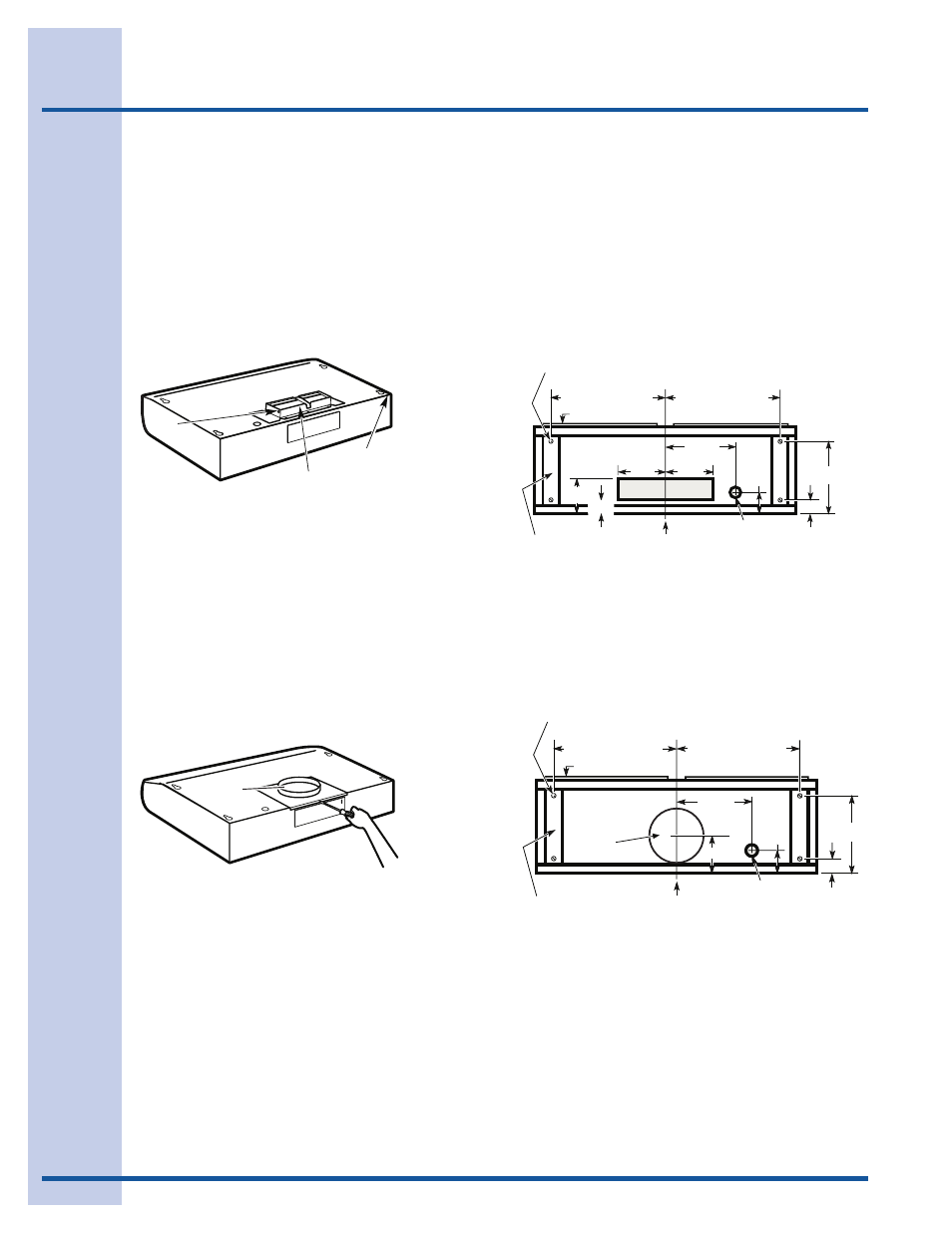
Outside top exhaust
Outside top exhaust
Outside top exhaust
Outside top exhaust
Outside top exhaust
(Vertical duct– 3 1/4”x 10” Rectangular)
Use the diagram or the hood as a template and mark
the locations on the cabinet for ductwork, electrical
wiring and keyhole screw slots.
Hood mounting screws (4)
1 1/4"
"
"
"
Center
line
Electrical access hole
(in cabinet bottom)
Wood shims (recessed
bottom cabinets only)
Vertical duct
access hole
13 15/16" (30" Hood)
16 15/16" (36" Hood)
13 15/16" (30" Hood)
16 15/16" (36" Hood)
Cabinet front
10 1/2"
Electrical access hole
(in cabinet bottom)
5"
1 1/4"
Cabinet Bottom
12 9/16"
5 1/4"
5 1/4"
2"
Outside top exhaust
Outside top exhaust
Outside top exhaust
Outside top exhaust
Outside top exhaust
(Vertical duct–7” Round)
Use the diagram or the hood as a template and
mark the locations on the cabinet for ductwork,
electrical wiring and keyhole screw slots.
Hood mounting screws (4)
1 1/2"
"
Center
line
Electrical access hole
(in cabinet bottom)
Wood shims (recessed
bottom cabinets only)
13 15/16" (30" Hood)
16 15/16" (36" Hood)
13 15/16" (30" Hood)
16 15/16" (36" Hood)
Cabinet front
10 1/2"
Electrical access hole
(in cabinet bottom)
Cabinet Bottom
12 1/2"
2 1/4"
8" DIA.
HOLE
5"
Access
hole for 7"
round duct
Installing the hood