Instructional booklet, Caution, Notice – Eaton Electrical Magnum Transfer Switch User Manual
Page 17: Fixed and drawout magnum transfer switches
IB01602011E
For more information visit: www.Eaton.com
Instructional Booklet
Effective: March 2007
Page 17
Fixed and Drawout Magnum Transfer Switches
4.3 Unpackaging and Inspection
Proceed with the following four steps:
Step 1: Carefully uncrate the transfer switch. If damage is visible,
please contact your local Eaton sales representative or the
factory.
Step 2: Open the door and visually verify that there are no broken
or damaged components or evidence of distorted metal or
loose wires as a result of rough handling.
Step 3: A label on the door provides specifications for your trans-
fer switch. Verify that these specifications comply with
your requirements.
Step 4: Remove any braces or packing used to protect the trans-
fer switch or internal components during shipping.
4.4 Mounting Procedure
With the enclosed transfer switch equipment unpacked and ready
for mounting, proceed with the following steps:
Step 1: Mounting and cabling access is best provided by remov-
ing side and rear covers (when applicable). See Section
9.3 for cover removal instructions.
Step 2: Gently maneuver the switch into its location using all of
the supplied lift brackets.
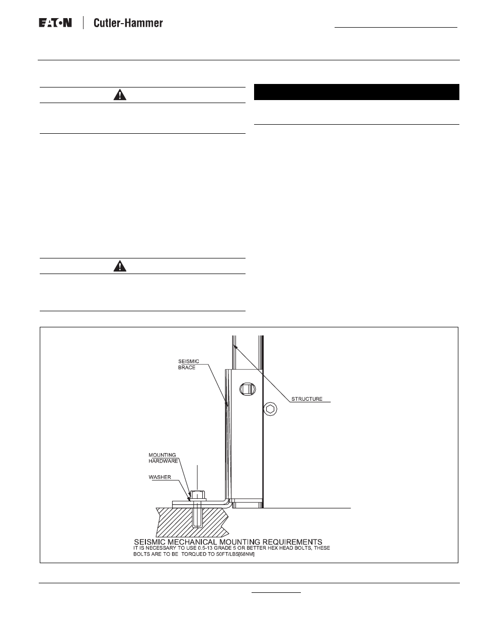
Step 3: Bolt the enclosure to the base. Use separate cleats
(Option 42 only) if Seismic Uniform Building Code (UBC)
Zone 4 certification is desired (Figure 20), and secure
with 1/2-13 UNC Grade 5 hex bolts.
Step 4: Tighten bolts to 50 ft-lbs (68 Nm).
Step 5: Double check to ensure that all packing and shipping
material has been removed
.
Figure 20. Seismic Tested and Approved Product Mounting Instructions.
CAUTION
SINCE THE ENCLOSED TRANSFER SWITCH MUST BE LIFTED INTO
PLACE FOR MOUNTING, BE CERTAIN THAT ADEQUATE RESOURCES
ARE AVAILABLE FOR LISTING TO AVOID PERSONNEL INJURIES OR
EQUIPMENT DAMAGE.
CAUTION
EXTREME CARE SHOULD BE TAKEN TO PROTECT THE TRANSFER
SWITCH FROM DRILL CHIPS, FILLINGS, AND OTHER CONTAMI-
NANTS WHEN MAKING THE CABLE ENTRY HOLES AND MOUNTING
THE ENCLOSURE TO PREVENT COMPONENT DAMAGE OR A
FUTURE MALFUNCTION.
NOTICE
CABLE ENTRY HOLES ARE NOT PART OF THE ENCLOSURE WHEN
SHIPPED FROM THE FACTORY AND MUST BE PROVIDED IN THE
FIELD, EITHER BEFORE OR AFTER MOUNTING THE ENCLOSURE.