Instructional booklet, Left side view (with panels removed), Fixed and drawout magnum transfer switches – Eaton Electrical Magnum Transfer Switch User Manual
Page 12
For more information visit: www.Eaton.com
IB01602011E
Instructional Booklet
Page 12
Effective: March 2007
Fixed and Drawout Magnum Transfer Switches
3.2.4 TRANSFER MECHANISM
The transfer switch uses Eaton Magnum insulated case switching
devices and insulated case switches with a stored-energy mecha-
nism. An electrical operator automatically recharges the mecha-
nism after the switching device has been closed, and an indicator
on the switch shows whether it is in the OPEN or CLOSED posi-
tion and the status of the stored energy mechanism.
The switching device is closed by energizing a solenoid that
releases the spring mechanism. A shunt trip will open the switch-
ing device if energized.
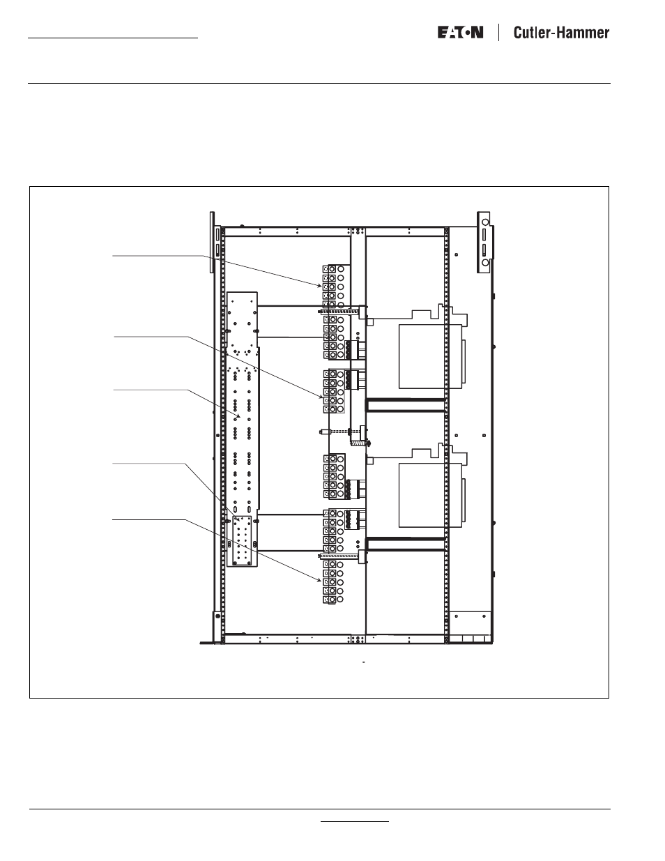
Figure 13. Terminal Connections for a Typical Drawout Transfer Switch (800-3200A Closed Transition Shown).
SOURCE 1
CABLE
CONNECTIONS
LOAD CABLE
CONNECTIONS
GROUND
CABLE
CONNECTIONS
SOURCE 2
CABLE
CONNECTIONS
LEFT SIDE VIEW (WITH PANELS REMOVED)
NEUTRAL CABLE
CONNECTIONS