EAW SB730 User Manual
Page 11
EAW KF730 & SB730 PRELIMINARY OWNER’S MANUAL Page 11 of 16
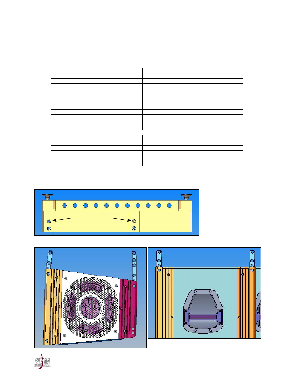
6.3.3 Hinge And Hinge Tube Holes
Each Hinge and Hinge Tube has several holes for inserting the supplied Connecting Pins to attach
enclosures together. The particular holes used determine the splay angles between the aiming axes of the
loudspeakers. The required splay angles are designated by the KF730 Wizard.
KF730 to Fly-Bar
1
Rear Hinge Hole
Rear Hinge Tube Hole Front Hinge Hole
Front Hinge Tube Hole
3 Upper 2
Upper
SB730 to Fly-Bar
1
Rear Hinge Hole
Rear Hinge Tube Hole Front Hinge Hole
Front Hinge Tube Hole
1 Upper 1
Upper
KF730 to KF730
2
Front Splay Angle
Rear Hinge Hole
Rear Hinge Tube Hole Front Hinge Hole
1.5° 1
A
2
3.0° 2
B
2
6.0° 3
B
2
12.0° 4
B
2
18.0° 4
B
1
KF730 to SB730
2
Front Splay Angle Rear Hinge Hole
Front Hinge Hole
-7.2° 1
2
-3.0° 2
2
0.0° 3
2
6.0° 4
2
12.0° 4
1
NOTES: 1. This positions the front face of the enclosure so it is 90° to the plane of the KF730 Fly-Bar.
2. The front splay angle is the angle between the aiming axes of the loudspeakers. It is not the splay
angle between the top/bottom enclosure surfaces.
KF730 FLY-BAR HINGE TUBE HOLES
KF730 AND SB730 HINGE AND HINGE TUBE HOLES
Hole 1
Hole 2
Hole 3
Hole 1
Hole 2
REAR
HINGE
TUBE
Hole A
Hole B
REAR
HINGE
FRONT
HINGE
Hole 1
Hole 2
Hole 1
Hole 2
FRONT
HINGE
REAR
HINGE
UPPER HOLES: USE THESE HOLES
FOR SUSPENSION
WARNING: USE LOWER HOLES
ONLY FOR GROUND STACKING