Installing the dram simm – Enterasys Networks 2G4072-52 User Manual
Page 66
Memory Locations and Replacement Procedures
B-8 Mode Switch Bank Settings and Optional Installations
3.
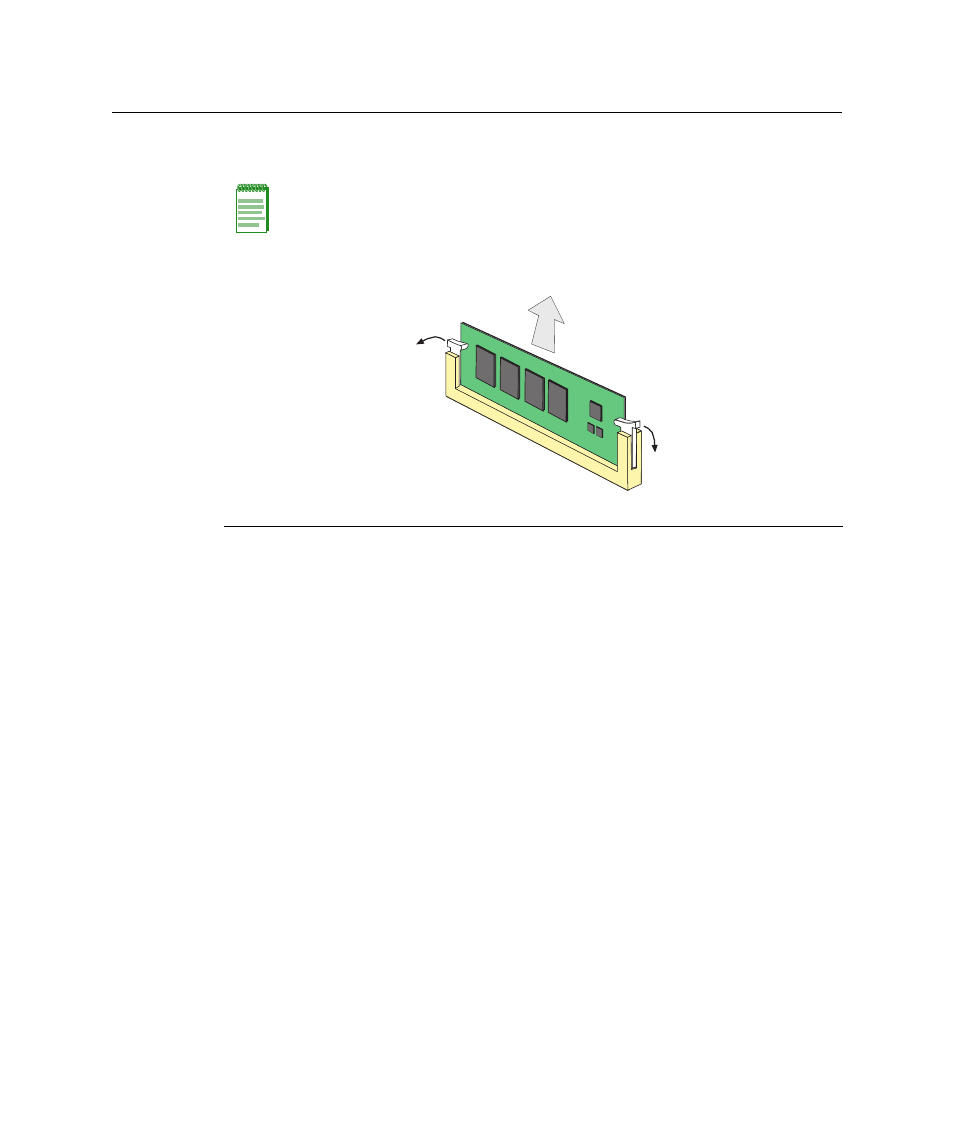
Push the connector arms away from the memory module to release the DRAM SIMM
from the connector, as shown in
Figure B-6 DRAM SIMM Connector Location
Installing the DRAM SIMM
To install the memory module, refer to
and proceed as follows:
1.
Push the connector arms away from the DRAM SIMM far enough to insert the DRAM
SIMM into the connector contacts.
2.
Insert the DRAM SIMM straight down between the connector contacts far enough for
the tabs on the connector arms to align with the two DRAM SIMM alignment notches.
3.
Push the DRAM SIMM down into the connector contacts. Then rotate the two
connector arms toward the DRAM SIMM to lock it into place.
Note: The ejector arms on this connector are not spring loaded, so they will remain in the
open position until manually closed.
1
Connector arms
2 DRAM SIMM
3 Connector contacts
Б
В
А
А