Connecting power, Connecting power -4, Ба а в в – Enterasys Networks 2G4072-52 User Manual
Page 30
Connecting Power
3-4 Installation
Connecting Power
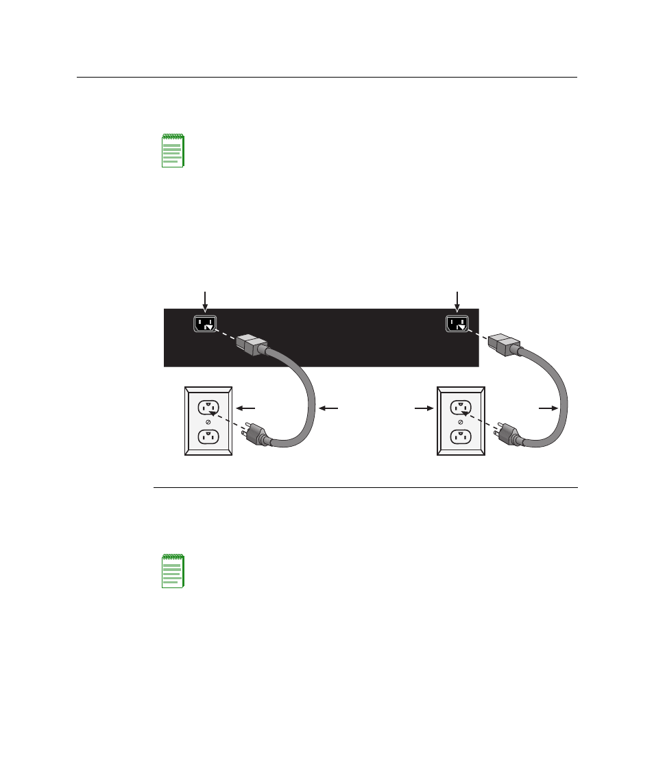
To connect the module to the power sources, refer to
To connect the module to the power sources, refer to
1.
Plug a power cord into each switch AC power receptacle. To take advantage of
redundancy capabilities, plug each power cord into a separate dedicated AC outlet.
2.
Plug the cord into a dedicated grounded AC outlet as shown in
.
Figure 3-3 Connecting Power
3.
Observe the LANVIEW LEDs. The Power (PWR) LED (not shown), located on the
front panel, turns ON (green) and the CPU turns red until the module completes its
initialization. It takes under 30 seconds for the module to boot up.
If the initialization process is successful, the CPU LED turns green. If the CPU LED does
not turn green, refer to
for troubleshooting information.
Note: The two power supplies in the module have automatic voltage sensing that allows
connection to power sources ranging from 100–125 Vac, 2.5 A or 200–240 Vac, 1.25 A,
50/60 Hz.
1 AC power cords
2 AC power outlets
3 AC power receptacles
Note: If the power-up sequence is interrupted on this device, or if optional hardware has
been installed or removed, this device may run an extended diagnostics sequence that
may take up to two minutes to complete.
AC INLET 1
100 - 125V ~ 3.6A
200 - 240V ~ 1.6A
50/60 Hz
AC INLET 2
100 - 125V ~ 1.8A
200 - 240V ~ 0.8A
50/60 Hz
Б
Б
А
А
В
В