Вб г г в – Enterasys Networks 2G4072-52 User Manual
Page 64
Memory Locations and Replacement Procedures
B-6 Mode Switch Bank Settings and Optional Installations
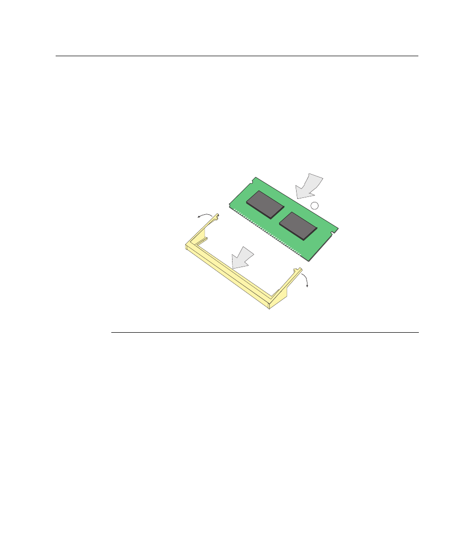
Installing the DIMM
1.
Insert the DIMM down between the connector fingers.
2.
Pivot the DIMM downward so the tabs on the connector arms align with the two
DIMM alignment notches. With the two connector arms spread outward, push the
DIMM down between the connector arms. Then release the two connector arms to
lock the DIMM into place.
Figure B-4 Installing the DIMM
3.
Replace the chassis cover by re‐attaching the provided screws.
1 DIMM
3 Connector arms
2 Connector fingers
4 SIMM alignment notches (2)
1
3535_01_15
В
Б
Г
Г
В