Sony X85K 50" 4K HDR Smart LED TV User Manual
Page 18
18
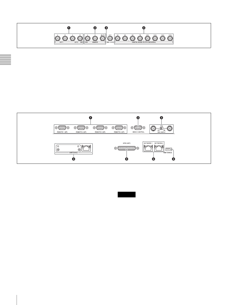
Connector Panel
Cha
p
te
r 2
Name
s
an
d F
unc
tions
of
P
a
rts
HD Output board (SRK-R202)
a
SD/HD SDI OUT A/B connectors
Output two sets of SD SDI or HD SDI video/audio signals.
Currently, only HD SDI signals are supported.
b
SD/HD SDI MONITOR A/B/MULTI connectors
Output the output signals for a monitor. Time data and
other character signals are superimposed and then output
when ALT/
[F10]
(CHAR ON) in the TC menu is set to On.
The MULTI connector currently cannot be used.
Currently, only HD SDI signals are supported.
c
TIME CODE OUT connector
Outputs the playback time code.
d
DIGITAL AUDIO OUTPUT (AES/EBU)
connector
Output the audio signals in AES/EBU format for channels
1 to 16.
B
Remote input/output section
a
REMOTE 1 to 4 (9-pin) connectors
To control the unit from an external device, connect it to
the external device with a remote control cable that has a
9-pin connector.
The Sony 9-pin VTR protocol and Sony 9-pin Disk
protocol are supported.
b
VIDEO CONTROL connector
Currently cannot be used.
c
REF. INPUT connectors and 75
Ω
terminal switch
Input the reference video signal of the selected field
frequency. Input an HD tri-level SYNC signal or SD black
burst signal.
A loop-through connection is also possible. Set the 75
Ω
terminal switch to OFF if you are using a loop-through
connection, and set it to ON if you are not using a loop-
through connection.
d
MAINTENANCE connector
Used by the administrator. This is not for normal use.
e
GPIO (25-pin) connector
Currently cannot be used.
f
NETWORK 1/2 connectors
Accepts a network cable for monitoring the unit by SNMP,
configuring or checking the unit via HTTP, transferring
files via FTP, etc.
• For safety, do not connect the connector for peripheral
device wiring that might have excessive voltage to this
connector.
Follow the instructions for this port.
• When you connect the network cable of the unit to
peripheral device, use a shielded-type cable to prevent
malfunction due to radiation noise.
CAUTION