Detailed explanation of each part – Roland TD-07DMK V-Drums Electronic Drum Set User Manual
Page 2
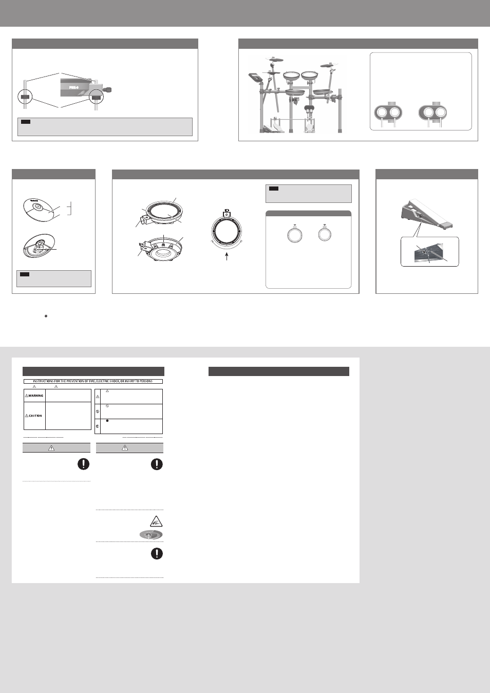
Detailed explanation of each part
CAUTION
Cautions when moving this unit
If you need to move the instrument, take note of
the precautions listed below. At least two persons
are required to safely lift and move the unit. It
should be handled carefully, all the while keeping
it level. Make sure to have a firm grip, to protect
yourself from injury and the instrument from damage.
• Check to make sure the bolts and hand knobs securing the
stand have not become loose. Fasten them again securely
whenever you notice any loosening.
• Disconnect the power cord.
• Disconnect all cords coming from external devices.
• Disconnect the kick pedal.
• Disconnect the connection cable of the kick pad.
• Disconnect the connection cable of the hi-hat control pedal.
Take care so as not to get fingers pinched
When handling the following moving parts, take
care so as not to get fingers, toes, etc., pinched.
Whenever a child uses the unit, an adult should be
on hand to provide supervision and guidance.
• Hi-hat control pedal
• Kick pedal
• Bottom of the cymbal pad (see figure)
Keep small items out of the reach of children
To prevent accidental ingestion of the parts listed
below, always keep them out of the reach of small
children.
• Included Parts
Cymbal nuts
• Removable Parts
Screws
CR2 plug’s cap
Used for instructions intended to alert the
user to the risk of injury or material
damage should the unit be used
improperly.
* Material damage refers to damage or
other adverse effects caused with
respect to the home and all its
furnishings, as well to domestic animals
or pets.
Used for instructions intended to alert the
user to the risk of death or severe injury
should the unit be used improperly.
The symbol alerts the user to things that must be
carried out. The specific thing that must be done is
indicated by the design contained within the circle. In the
case of the symbol at left, it means that the power-cord
plug must be unplugged from the outlet.
The symbol alerts the user to important instructions or
warnings.The specific meaning of the symbol is
determined by the design contained within the triangle. In
the case of the symbol at left, it is used for general
cautions, warnings, or alerts to danger.
The symbol alerts the user to items that must never be
carried out (are forbidden). The specific thing that must
not be done is indicated by the design contained within
the circle. In the case of the symbol at left, it means that
the unit must never be disassembled.
About WARNING and CAUTION Notices
About the Symbols
ALWAYS OBSERVE THE FOLLOWING
9
CY-5 (Hi-hat/Crash/Ride)
NOTE
Continuous playing may cause dis-coloration of the pad,
but this will not affect the pad’s function.
Component names
Component names
NOTE
5
Be sure to adjust the head tension of the pad before use.
5
PDX-6A does not support the use of the rim-shot technique.
9
PDX-8 (Snare) / PDX-6A (Tom)
9
Hi-hat control pedal
9
PDX-8 (Snare)
9
PDX-6A (Tom)
9
About the memory clamp
The memory clamp aligns the pad at a fixed height when it is attached.
When shipped, the memory clamp is attached at the recommended position for using the drum safely.
NOTE
If the memory clamp is moved or removed in order to adjust the position of the PDX-8 (snare), a greater length of the rod may protrude;
take care that the protruding rod does not cause injury.
PDX-8
Pad face
Bow
Edge
OUTPUT jack
Knob bolt
Head
Tuning bolts
OUTPUT jack
Hoop rubber
Shell
Holder
Suitable position
for rim shots
Player
Position the two beaters equally apart from the center of the pad as shown in
the figure below. If one of the beater is further away from the center than the
other, the sound from the further beater will be lower in volume, or will not
sound as desired.
If you’re using twin pedals, the sensitivity will be lower than when a single
pedal is used. Raise the sensitivity on the sound module.
For details, refer to “TD-07 Owner’s Manual.”
Adjusting the head tension
1.
Use the drum key to adjust each tuning bolt a little at a
time, moving in order from one side to the opposite side as
shown in the illustration.
The appropriate amount of tension is one that will provide
approximately the same striking response as on an acoustic
drum.
2.
Make minor adjustments to the tightness as necessary.
Correct positioning
Incorrect positioning
Placement
• Depending on the material and temperature of the surface on
which you place the unit, its rubber feet may discolor or mar
the surface.
Additional Precautions
• This instrument is designed to minimize the extraneous sounds
produced when it’s played. However, since sound vibrations
can be transmitted through floors and walls to a greater degree
than expected, take care not to allow these sounds to become
a nuisance others nearby.
569
• The rubber portion of the striking surface is treated with a
preservative to maintain its performance. With the passage of
time, this preservative may appear on the surface as a white
stain, or reveal how the pads were struck during product
testing. This does not affect the performance or functionality of
the product, and you may continue using it with confidence.
• Continuous playing may cause dis-coloration of the pad, but
this will not affect the pad’s function.
• This document explains the specifications of the product
at the time that the document was issued. For the latest
information, refer to the Roland website.
Intellectual Property Right
• Roland and V-Drums are either registered trademarks or
trademarks of Roland Corporation in the United States and/or
other countries.
• Company names and product names appearing in this
document are registered trademarks or trademarks of their
respective owners.
USING THE UNIT SAFELY
IMPORTANT NOTES
WARNING
Use only the supplied AC adaptor and the correct voltage
Be sure to use only the AC adaptor supplied with
the unit. Also, make sure the line voltage at the
installation matches the input voltage specified on
the AC adaptor’s body. Other AC adaptors may use
a different polarity, or be designed for a different
voltage, so their use could result in damage, malfunction, or
electric shock.
4
3
2
5
6
1
4
1
2
3
5
PDX-8
PDX-6A
Rod
(pad mount)
Memory clamp
PDX-8
OUTPUT jack
Rear side
Engage cable
with slot
* Depending on how the drums are set up and played, some pads might be triggered unintentionally or one of the pads might not respond when two pads are struck at the same time.
In this case, press the [ ] (SETUP) button on the sound module, select “PAD,” select “ADVANCED,” and adjust the “XtlkCancel” parameter. For details, refer to “TD-07 Owner’s Manual.”