100base-fx expansion module – Enterasys Networks X-Pedition 2000 User Manual
Page 52
Installing the Hardware
36
Enterasys Xpedition 2000 Getting Started Guide
shows the pin positions in the 10/100BASE-TX connectors.
Figure 19. 10/100BASE-TX RJ-45 connector
2.
Make sure the TXD signal from the port emerges as an RXD signal on the switch, router, or
host on the other end of the segment cable. Likewise, make sure the TXD signal from the port
emerges as an RXD signal on the other end of the segment.
3.
Plug one end of the cable into the port and the other end of the cable into the device at the other
end of the connection.
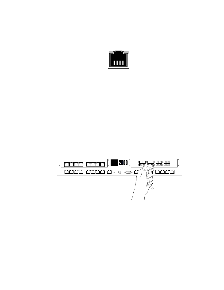
100BASE-FX Expansion Module
The 100BASE-FX expansion module supports multimode fiber (MMF).
shows where to
plug your fiber cable into a port on the 100BASE-FX expansion module.
The procedure following the figures describes how to set up and insert the cables.
Figure 20. Plugging an ethernet cable into a 100BASE-FX expansion module port
The 100BASE-FX expansion module uses SC-style Media Interface Connectors (MICs) to attach
to multimode fiber (MMF) cables.
To attach the segment cables to your 100BASE-FX expansion module, obtain an MMF cable with
an SC MIC and plug the MIC into the port connector. When you plug the other end of the cable into
another device, ensure that the cable connected to the transmit port on the XP is connected to the
receive port on the other device. The receive port on the XP should be connected to the transmit
port on the other device.
87654321
8
7
6
5
4
3
2
1
8
7
6
5
4
3
2
1
100BASE-FX
8
7
6
5
4
3
2
1
10/100BASE-TX
1
3
2
4
CONSOLE
10/100 MGMT
OK
ERR
DIAG
HBT
RST
G2M-HTXA2-08
G2M-HFXA4-08
10/100BASE-TX
10/100BASE-TX
8
7
6
5
4
3
2
1
Act
Lnk
Lnk
Act
Lnk
Lnk
Act
Lnk
Lnk
Act
Lnk
Lnk
G20-B
SYS
Enterasys Networks