Input and output data images – ProSoft Technology 5210-DFNT-RIO User Manual
Page 26
RIO ♦ ProLinx Gateway
Ladder Programming for RIO Module
Rockwell Automation® Remote I/O Adapter
Driver Manual
Page 26 of 39
ProSoft Technology, Inc.
February 4, 2010
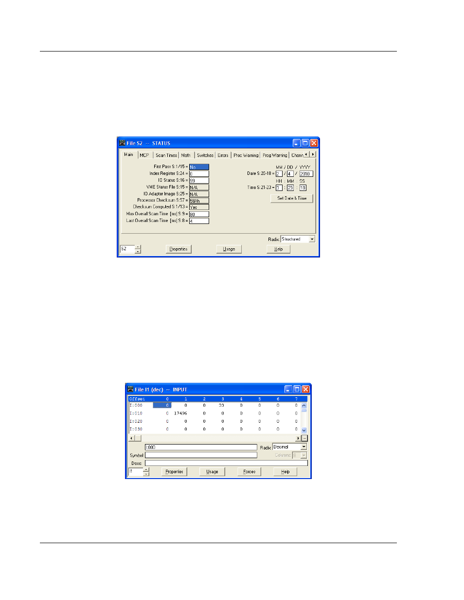
This example setup defines the module to be a full rack (8-input words and 8-
output words) at rack address 1, group 0. You must define the configuration and
I/O status files when installing and configuring the module. The configuration file
is defined in the field shown in the display above (Diagnostic File: 101 in the
example). The RSLogix software will automatically generate this file. The I/O
status file is defined in the controller setup dialog box displayed below (I/O Status
S:16 = 99):
6.2
Input and Output Data Images
Data in the input and output images is automatically transferred between the
module and the PLC. Therefore, no ladder logic is required to interface with this
data. The input and output map information in the ProLinx module’s configuration
file (RIOMCM.CFG) defines the source and destination of this data. Each word in
the I/O image is assigned by the user to be associated with a register in the
module’s virtual database.
Using the configuration defined above, the input image data will be stored in the
PLC data table I1:010 to I1:017. Data in the table is sourced from the module and
placed in the data table by the RIO driver. An example of the file is shown below: