Main logic loop, Processor not in run, Backplane data transfer – ProSoft Technology MVI46-MBP User Manual
Page 40
MVI46-MBP ♦ SLC Platform
Reference
Modbus Plus Communication Module
Page 40 of 101
ProSoft Technology, Inc.
February 19, 2008
After the module receives the module configuration from the processor, the
Modbus Plus chipset is enabled (presuming valid configuration values were
received), and begins communicating with other nodes on the network,
depending on the configuration.
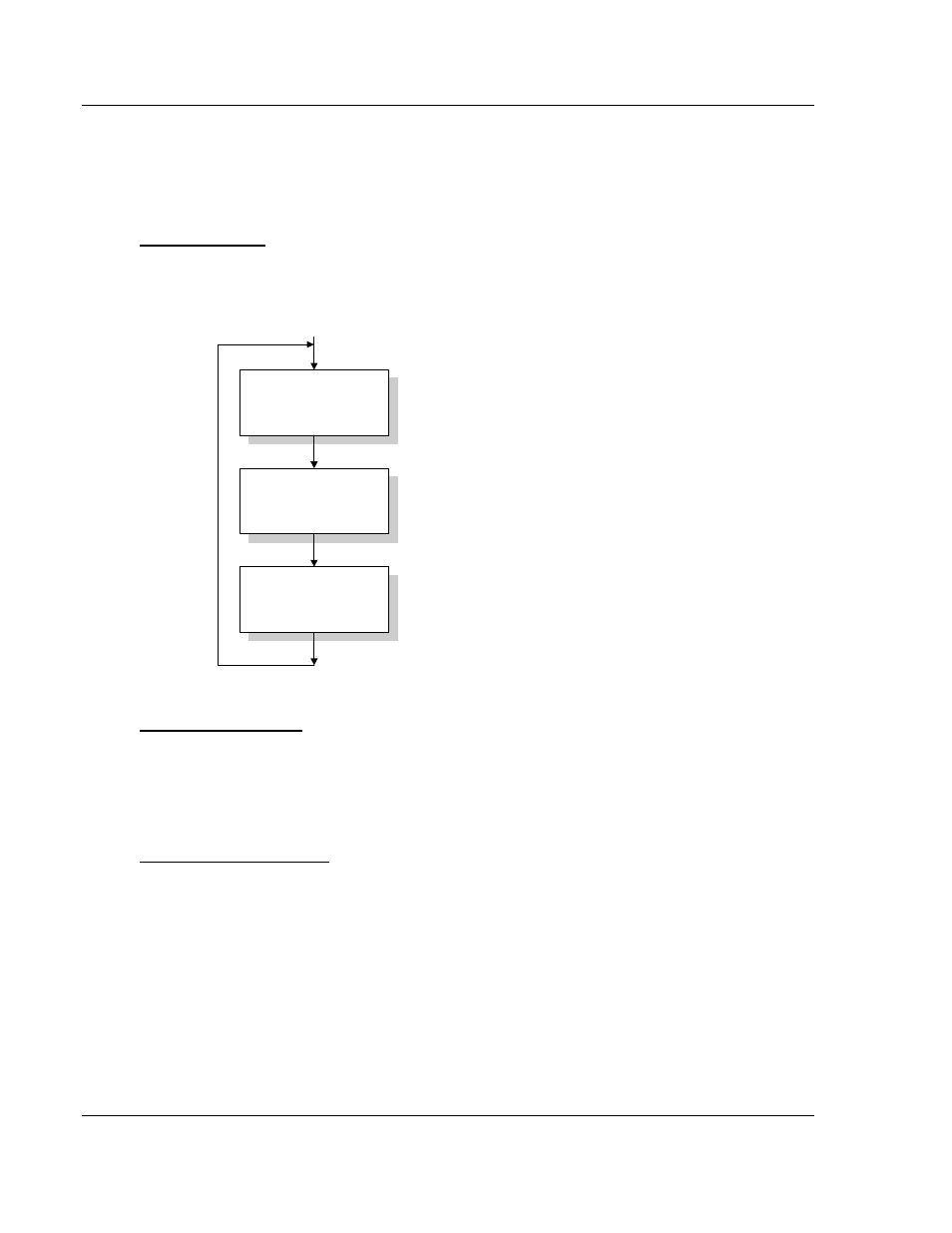
Main Logic Loop
Upon completing the power up configuration process, the module enters an
infinite loop that performs the following functions:
Call I/O Handler
Call CFG/DEBUG Port
Driver
Call Network Master &
Slave Drivers
Call I/O Handler
Transfers data between the module and processor
(user, status, etc.)
Call Serial Port Driver
Rx and Tx buffer routines are interrupt driven. Call to
serial port routines check to see if there is any data
in the buffer, and depending on the value, will either
service the buffer or wait for more characters.
Call Network Master & Slave Drivers
Generate messages and
respond to messages received.
From Power Up Logic
Processor Not in Run
Whenever the module detects that the processor has gone out of the Run mode
(that is, Fault or PGM), the Modbus Plus port can be shut down as prescribed in
the user configuration. When the processor is returned to a running state, the
module resumes communications on the network.
Backplane Data Transfer
The MVI46-MBP module communicates directly over the SLC backplane. All data
for the module is contained in the module's M0 and M1 files and the input and
output files. Data is moved between the module and the SLC processor across
the backplane using the module's M-files. The SLC scan rate and the
communication load on the module determine the update frequency of the M1
file. The COP instruction can be used to move data between user data files and
the module's M0 file and the M1 file and the user files. All register data travels
between the module and the processor using the M1 file. The M0 file is used for
special command control of the module from the ladder logic. High-speed data
transfer between the processor and the module is accomplished using the
module's input and output files.