Setting up a connection with the module – ProSoft Technology MVI56E-LDM User Manual
Page 14
Preparing the MVI56E-LDM Module
ControlLogix Platform ♦ "C" Programmable
Developer's Manual
Linux Application Development Module
Page 8 of 264
ProSoft Technology, Inc.
March 12, 2014
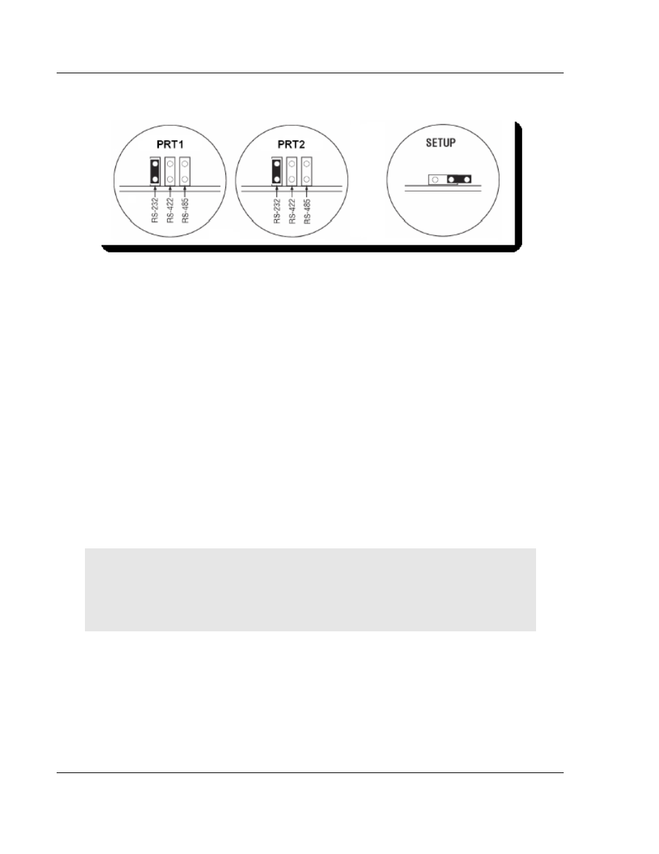
Port 1
Port 2
2.4.1 Setup Jumper - MVI56E
The Setup Jumper acts a write protection for the module's firmware. In "write-
protected" mode, the setup pins are not connected which prevents the module's
firmware from being overwritten.
The module is shipped with the Setup Jumper OFF. If you need to update the
firmware or run a module rescue (recovery), apply the setup shunt over both
pins.
2.4.2 Port 1 and Port 2 Jumpers MVI56E
These jumpers, located at the bottom of the module, configure the port settings
to RS-232, RS-422, or RS-485. By default, the jumpers for both ports are set to
RS-232.
2.5
Setting Up a Connection with the Module
If you have not already done so, please install and configure your ControlLogix
processor and power supply. Refer to the Rockwell Automation product
documentation for installation instructions.
Warning: You must follow all safety instructions when installing this or any other electronic
devices. Failure to follow safety procedures could result in damage to hardware or data, or even
serious injury or death to personnel. Refer to the documentation for each device you plan to
connect to verify that suitable safety procedures are in place before installing or servicing this
device.
After verifying proper jumper placement, insert the module into the ControlLogix
chassis. Use the same technique recommended by Rockwell Automation to
remove and install ControLogix modules.