ProSoft Technology MVI69-GSC User Manual
Page 53
MVI69-GSC ♦ CompactLogix or MicroLogix Platform
Ladder Logic
Generic ASCII Serial Communication Module
User Manual
ProSoft Technology, Inc.
Page 53 of 102
September 24, 2010
3.3
Adjust the Input and Output Array Sizes (Optional)
The module internal database is divided into two user-configurable areas:
Read Data
Write Data.
The Read Data area is moved from the module to the processor, while the Write
Data area is moved from the processor to the module. You can configure the
start register and size of each area. The size of each area you configure must
match the Add-On instruction controller tag array sizes for the R
EAD
D
ATA
and
W
RITE
D
ATA
arrays.
The MVI69-GSC sample program is configured for 600 registers of R
EAD
D
ATA
and 600 registers of W
RITE
D
ATA
,
which is sufficient for most application. This
topic describes how to configure user data for applications requiring more than
600 registers of ReadData and WriteData.
Important: Because the module pages data in blocks of 200 registers at a time, you must
configure your user data in multiples of 200 registers.
Caution: When you change the array size, RSLogix may reset the tag values to zero. To avoid
data loss, be sure to save your settings before continuing.
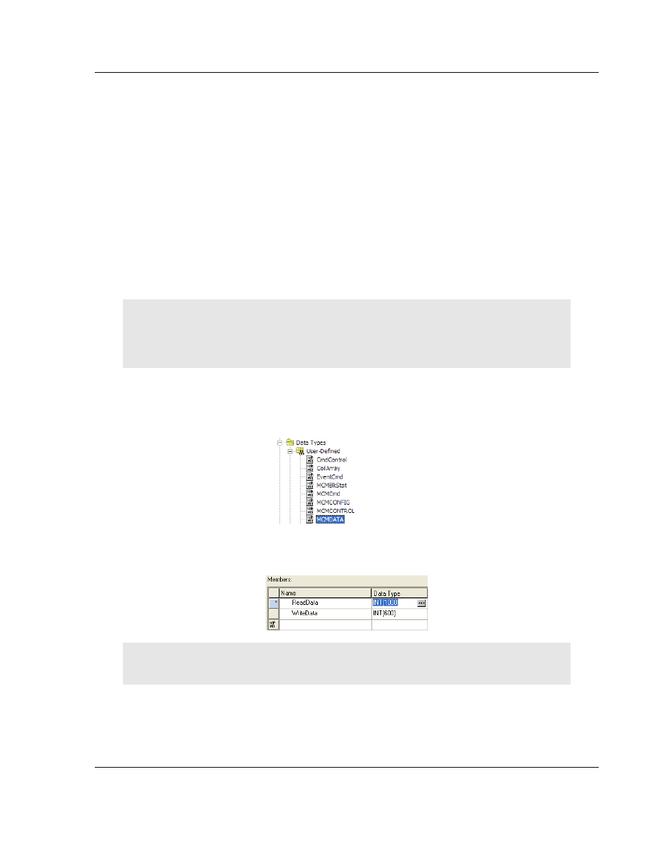
1 In the C
ONTROLLER
O
RGANIZATION
window, expand the D
ATA
T
YPES
and
U
SER
-D
EFINED
folders, and then double-click DATA.
This action opens an
edit window for the DATA data type.
2 In the edit window, change the value of the R
EAD
D
ATA
array from INT[600] to
INT[1000] as shown, and then click A
PPLY
.
Note: If RSLogix resets your data values, refer to the backup copy of your program to re-enter your
configuration parameters.
3 Next, navigate to C
ONTROLLER
T
AGS
and double click to open an edit
window. Click the M
ONITOR
T
AGS
tab at the bottom of the edit window.